Cooling roller surface processing technology
A technology of surface processing and cooling roll, applied in the field of cooling roll surface processing technology and metal surface processing technology, to achieve the effect of improving hardness and fatigue resistance, and reducing surface roughness.
- Summary
- Abstract
- Description
- Claims
- Application Information
AI Technical Summary
Problems solved by technology
Method used
Image
Examples
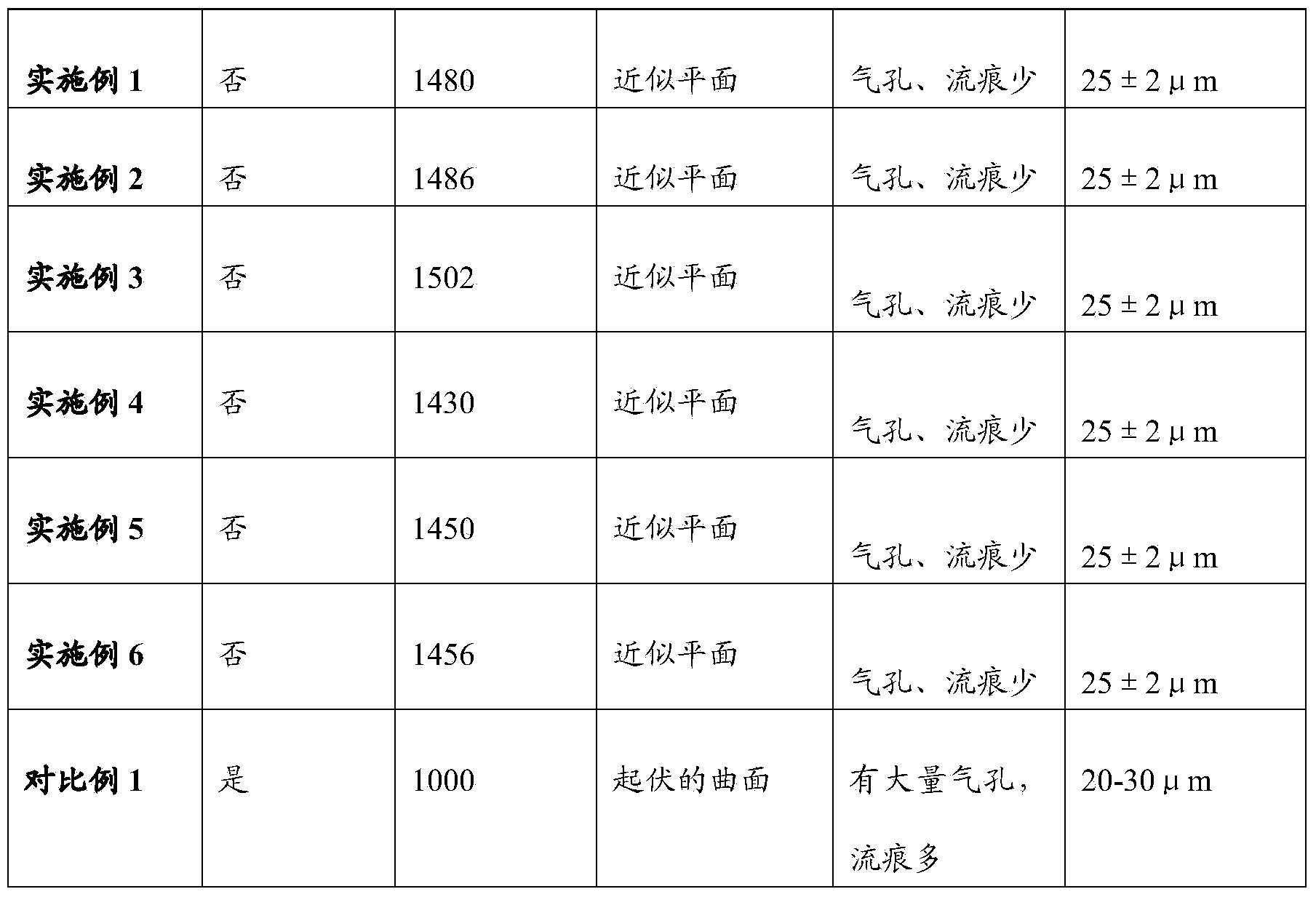
Embodiment 1
[0023] (1) Cut the surface of the copper roller sleeve of the cooling roller to remove the unevenness that can be observed by the naked eye;
[0024] (2) the copper roller sleeve is fixed on the rotating shaft to make it rotate at a rotational speed of 60rpm;
[0025] (3) Shot blasting is carried out to the roller sleeve surface in rotation, and described shot peening is the amorphous powder of particle diameter 0.01mm, and the included angle of nozzle extension line and shot peening tangent at the roller sleeve surface impact point place is 50 °, The injection direction is the same as the rotation direction of the roller sleeve, the injection distance is 60mm, the injection pressure is 0.8MPa, and the shot peening time is 15min;
[0026] (4) Carry out rolling treatment on the surface of the rotating roller sleeve by mechanical rolling, the rolling force is 400N, the rolling speed is 10m / min, and the rolling times are 2 times;
[0027] (5) Before the cooling roll is used, an ...
Embodiment 2
[0029] (1) Cut the surface of the copper roller sleeve of the cooling roller to remove the unevenness that can be observed by the naked eye;
[0030] (2) the copper roller sleeve is fixed on the rotating shaft to make it rotate, and the rotation speed is 65rpm;
[0031] (3) Shot blasting is carried out to the roller cover surface in rotation, and described shot peening is the Al-Ni-Y amorphous powder of particle diameter 0.02mm, and the clip of nozzle extension line and shot peening is at the impact point place tangent line of roller cover surface The angle is 55°, the injection direction is the same as the rotation direction of the roller sleeve, the injection distance is 70mm, the injection pressure is 0.7MPa, and the shot peening time is 10min;
[0032] (4) Carry out rolling treatment on the surface of the rotating roller sleeve by mechanical rolling, the rolling force is 300N, the rolling speed is 11m / min, and the rolling frequency is 1 time;
[0033] (5) Before the cooli...
Embodiment 3
[0035] (1) Cut the surface of the copper roller sleeve of the cooling roller to remove the unevenness that can be observed by the naked eye;
[0036] (2) the copper roller cover is fixed on the rotating shaft to make it rotate at a rotational speed of 70rpm;
[0037] (3) Shot blasting is carried out to the roller cover surface in rotation, and described shot peening is the Al-Ni-La amorphous powder of particle diameter 0.03mm, and the clip of nozzle extension line and shot blasting tangent at the roller cover surface impact point place The angle is 60°, the injection direction is the same as the rotation direction of the roller sleeve, the injection distance is 100mm, the injection pressure is 0.9MPa, and the shot peening time is 20min;
[0038] (4) Carry out rolling treatment on the surface of the rotating roller sleeve by mechanical rolling, the rolling force is 350N, the rolling speed is 12m / min, and the rolling times are 3 times;
[0039] (5) Before the cooling roll is us...
PUM
| Property | Measurement | Unit |
|---|---|---|
| Surface roughness | aaaaa | aaaaa |
| Surface roughness | aaaaa | aaaaa |
| Surface roughness | aaaaa | aaaaa |
Abstract
Description
Claims
Application Information
 - R&D
- Intellectual Property
- Life Sciences
- Materials
- Tech Scout
- Unparalleled Data Quality
- Higher Quality Content
- 60% Fewer Hallucinations
Browse by: Latest US Patents, China's latest patents, Technical Efficacy Thesaurus, Application Domain, Technology Topic, Popular Technical Reports.
© 2025 PatSnap. All rights reserved.Legal|Privacy policy|Modern Slavery Act Transparency Statement|Sitemap|About US| Contact US: help@patsnap.com


