
Galvanometer and laser radar

A light source and reflector technology, applied in the field of laser radar, can solve the problems of MEMS vibrating mirror being easily affected by vibration, poor reliability of MEMS vibrating mirror, easy to be damaged by vibration or impact, etc., so as to prolong life, improve reliability and improve resistance Effects of Vibration and Shock Capability

Pending Publication Date: 2020-03-31
LEISHEN INTELLIGENT SYST CO LTD
View PDF12 Cites 3 Cited by
  • Summary
  • Abstract
  • Description
  • Claims
  • Application Information

AI Technical Summary

Problems solved by technology

However, this kind of torsion beam has low stiffness, and it is prone to stress concentration in the external vibration environment and exceeds the stress limit of the material, resulting in damage to the MEMS vibrating mirror; or, due to the low stiffness, the MEMS vibrating mirror is easily affected by vibration
As a result, the reliability of the MEMS galvanometer is poor, and it is easily damaged by vibration or shock, resulting in a short life of the lidar

Method used


Image

  • Galvanometer and laser radar
  • Galvanometer and laser radar
  • Galvanometer and laser radar

Examples


Embodiment Construction

[0031] The present invention will be further described in detail below in conjunction with the accompanying drawings and embodiments. It should be understood that the specific embodiments described here are only used to explain the present invention, but not to limit the present invention. In addition, it should be noted that, for the convenience of description, only some structures related to the present invention are shown in the drawings but not all structures.

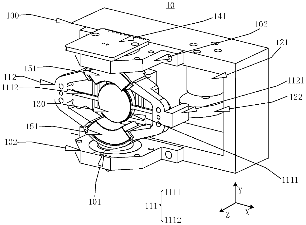
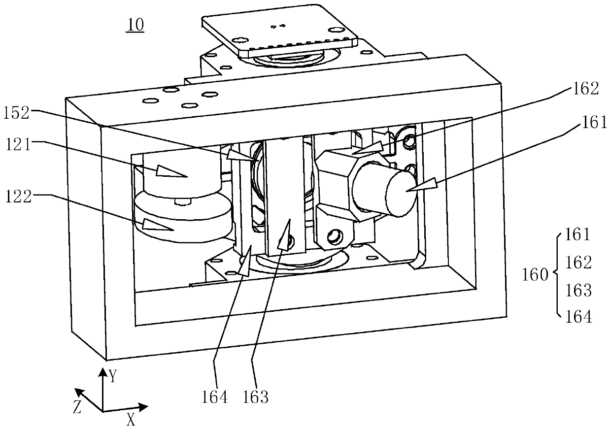
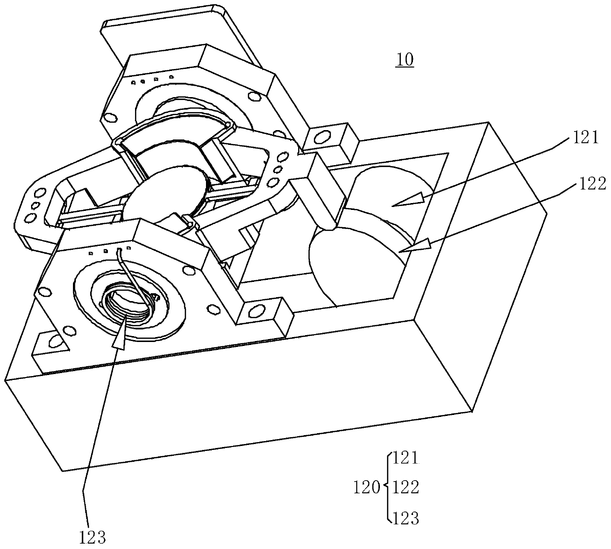
[0032] The vibrating mirror (also referred to as "scanning vibrating mirror") provided by the embodiment of the present invention is mainly used in solid-state or hybrid solid-state lidar. By controlling the mirror in the scanning vibrating mirror to rotate around the fast axis, the The laser beam projected on the mirror is reflected to the vertical field of view, thereby realizing slow-axis scanning; by controlling the mirror in the scanning galvanometer to rotate around the slow axis, the laser beam projected to ...


PUM


Abstract

The invention discloses a galvanometer and a laser radar, and the galvanometer comprises a fixed seat, a galvanometer drive frame which comprises a fast-axis support, a slow-axis support and a fast-axis frame, a reflector is installed in the fast-axis frame of the fast-axis support, the fast-axis support is connected in the slow-axis support, and the galvanometer drive frame is rotatingly connected in the fixed seat; the fast shaft frame twists around a first direction, and the slow shaft frame twists around a second direction; the slow shaft driving assembly comprises a motor and a cam; the cam is connected with the motor, the edge of the cam abuts against the side face of one end of the slow-axis support, and the motor drives the cam to rotate in the second direction and drives the slow-axis support to rotate in the second direction. Therefore, the reliability of the galvanometer can be improved, the vibration and impact resistance of the galvanometer is improved, and the service life of the laser radar is prolonged.

Description

technical field [0001] Embodiments of the present invention relate to the technical field of laser radar, and in particular, to a vibrating mirror and laser radar. Background technique [0002] Lidar is a radar system that emits laser beams to detect the position, speed and other characteristic quantities of target objects. With the development of lidar, micro-electro-mechanical system (Micro-Electro-Mechanical System, MEMS) vibrating mirror (also referred to as "vibrating mirror" in this article) is applied to lidar, and the development of solid-state lidar has become the focus of lidar in recent years. Develop new trends. MEMS oscillating mirror is a kind of micromirror made by MEMS technology. Its working mode is mostly resonant mode, which has the advantages of small size, high oscillation frequency, and no rotating parts. [0003] In general, solid-state LiDAR favors electromagnetic MEMS galvanometers and MEMS-like galvanometers. Electromagnetic MEMS vibrating mirror...

Claims


Application Information

Patent Timeline
Patent Type & Authority Applications(China)
IPC IPC(8): G01S17/02G01S7/481
CPCG01S17/02G01S7/4817
Inventor 郭丰收刘立福
Owner LEISHEN INTELLIGENT SYST CO LTD
Learn More