A docking station for quartz rods

A quartz rod and docking table technology, applied in the field of lithography, can solve the problems that the edge of the end face is difficult to be absolutely vertical, the edge of the quartz rod is collapsed, and the precision is high, so as to avoid the contact between the butt surface and the edge of the side and reduce the collapse of the edge. Probability, the effect of ensuring the quality of docking

Active Publication Date: 2021-07-13
SHANGHAI MICRO ELECTRONICS EQUIP (GRP) CO LTD
View PDF6 Cites 0 Cited by
  • Summary
  • Abstract
  • Description
  • Claims
  • Application Information

AI Technical Summary

Problems solved by technology

However, due to the long required length and high precision of quartz rods, it is difficult to process the whole rod under existing conditions. Two or more quartz rods are usually spliced ​​to obtain the required length of quartz rods.
[0004] During the processing of quartz rods, due to the influence of machining accuracy, it is difficult to achieve absolute perpendicularity between the end edge and the side edge, and because the quartz rod is a brittle material and the docking process is rigid contact, when the docking process occurs, a When the butt end face of the quartz rod is in contact with the side edge of another quartz rod, the quartz rod is prone to edge chipping, and even a very small edge chipping will have a great impact on the uniform light effect of the quartz rod, thereby reducing the quality of the quartz rod. Excellent dodging quality and light uniformity of the lighting system

Method used


Image

  • A docking station for quartz rods
  • A docking station for quartz rods

Examples


Embodiment Construction

[0029] The present invention will be further described in detail below in conjunction with the accompanying drawings and embodiments. It should be understood that the specific embodiments described here are only used to explain the present invention, but not to limit the present invention. In addition, it should be noted that, for the convenience of description, only some structures related to the present invention are shown in the drawings but not all structures.

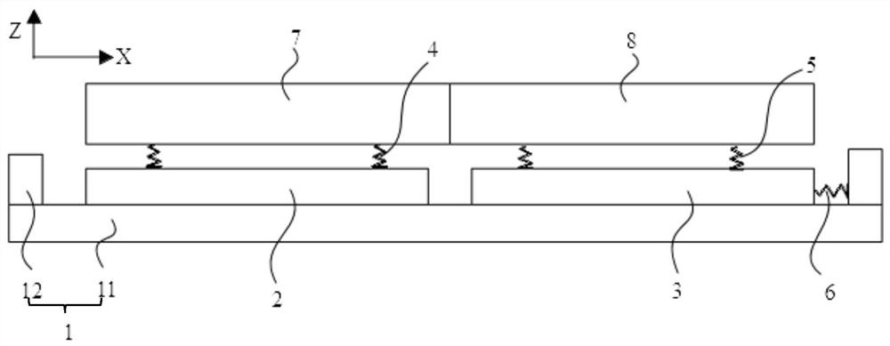
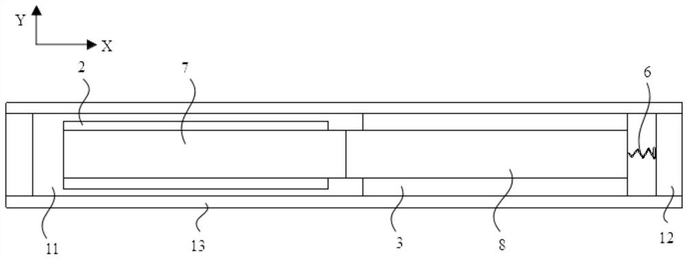
[0030] figure 1 The front view of the quartz rod docking platform provided by the embodiment of the present invention, figure 2 The top view of the quartz rod docking station provided for the embodiment of the present invention, as figure 1 and 2 As shown, this embodiment provides a docking platform for quartz rods, including a base 1 , a first installation platform 2 and a second installation platform 3 . The lower surface of the first installation table 2 is connected to the base 1, and can slide in the firs...


PUM


Abstract

The invention relates to a docking platform for quartz rods, which includes a base; a first installation platform, the lower surface of which is connected to the base and can slide relative to the base in a first horizontal direction; the upper surface of the first installation platform is connected to the base The lower end of the first elastic element is connected, and the upper end of the first elastic element is used to connect the first quartz rod; the second installation platform, its lower surface is connected with the base, and the upper surface of the second installation platform is connected with the first The lower end of the two elastic elements, the upper end of the second elastic element is used to connect the second quartz rod, the second mounting platform is adjacent to the first mounting platform in the first horizontal direction, and the One end of the first quartz rod faces the second quartz rod. The quartz rod docking platform provided by the present invention can reduce the chipping probability during the docking process of the quartz rods, and ensure the docking quality of the quartz rods and the uniform light effect of the quartz rods.

Description

technical field [0001] The invention relates to the technical field of photolithography, in particular to a docking platform for quartz rods. Background technique [0002] A photolithography system usually includes an illumination system, a reticle containing a circuit pattern, a projection system, and a silicon wafer for coating photoresist and a silicon wafer alignment table. The image of the template circuit diagram is projected onto the wafer, so that the circuit diagram on the reticle can be obtained after the wafer is etched. In order to ensure the quality of lithography, it is required that the light intensity distribution in the illumination field of view of the illumination system be uniform. [0003] In the lighting system, the main function of the quartz rod is to reflect the light beam emitted by the light source multiple times to obtain a uniform light beam. The dodging effect of the quartz rod is related to the coherence factor of the lighting system. When th...

Claims


Application Information

Patent Timeline
Patent Type & Authority Patents(China)
IPC IPC(8): G03F7/20
CPCG03F7/70058G03F7/70075
Inventor 马忠良高沛
Owner SHANGHAI MICRO ELECTRONICS EQUIP (GRP) CO LTD
Why Eureka
Try Eureka