Self-floating waterproof control cabinet of water pump

A control cabinet and self-floating technology, applied in pump control, casing/cabinet/drawer parts, electrical equipment casing/cabinet/drawer, etc., can solve long troubleshooting period, cumbersome maintenance, electric shock accidents, etc. problems, to achieve the effect of prolonging the submersion time, protecting life safety, and preventing water leakage

Pending Publication Date: 2020-03-31
江苏富亚给排水科技有限公司
View PDF0 Cites 0 Cited by
  • Summary
  • Abstract
  • Description
  • Claims
  • Application Information

AI Technical Summary

Problems solved by technology

The biggest trouble for buried equipment is that the potential of the control cabinet system is low, and it is easily affected by the seepage of pools, surface water, and floods. In the event of water seepage in the pump room, the control cabinet is likely to be submerged in water, resulting in damage to the control components. In the fire protection system It is impossible to ensure the reliable start and operation of the fire pump, and the maintenance is relatively cumbersome and the troubleshooting period is long. There are serious fire hazards and serious electric shock accidents, which bring a lot of inconvenience to users and unnecessary economic losses to users.
[0003] Traditional control cabinets are mostly fixedly connected to the sunken ground of the pump room. When a water seepage accident occurs, the control cabinet will come into contact with water, which may cause leakage and damage to the internal structure of the cabinet, and some self-floating cabinets There is no guiding mechanism and buffer device, and it may touch obstacles such as walls when floating, causing damage to internal components of the cabinet, or causing the cabinet to fall and be submerged in water

Method used


Image

  • Self-floating waterproof control cabinet of water pump
  • Self-floating waterproof control cabinet of water pump
  • Self-floating waterproof control cabinet of water pump

Examples


Embodiment Construction

[0019] The technical solutions in the embodiments of the present invention will be clearly and completely described below in conjunction with the accompanying drawings in the embodiments of the present invention. Obviously, the described embodiments are only a part of the embodiments of the present invention, rather than all the embodiments. Based on the embodiments of the present invention, all other embodiments obtained by those of ordinary skill in the art without creative work shall fall within the protection scope of the present invention.

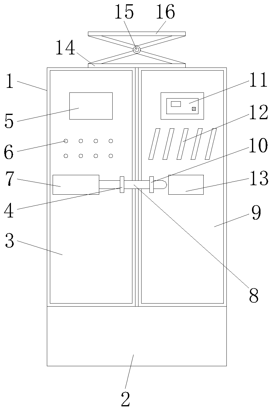
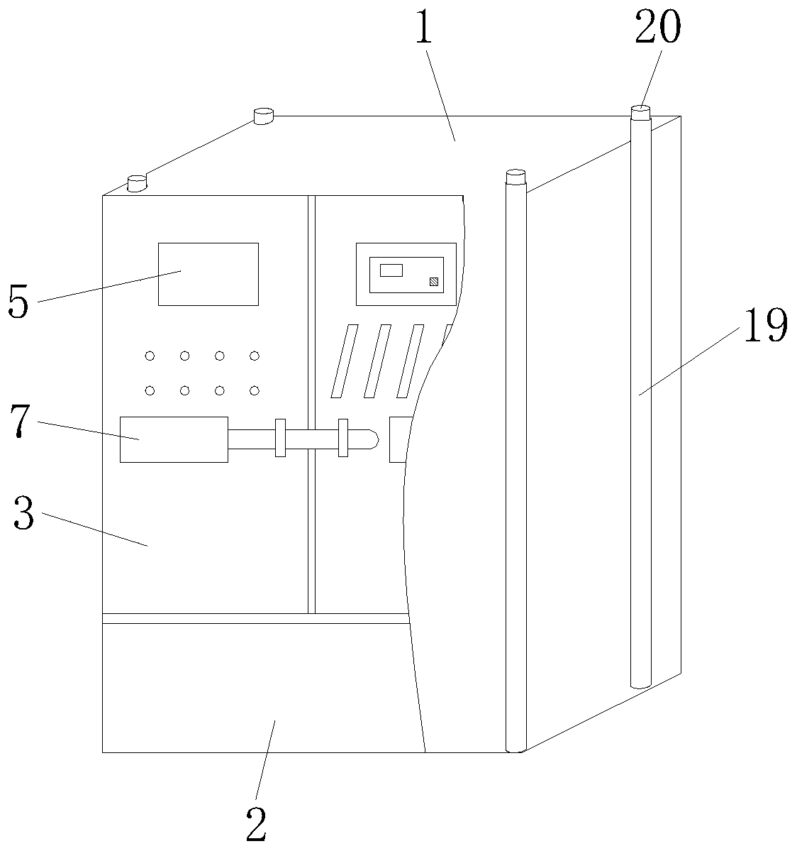
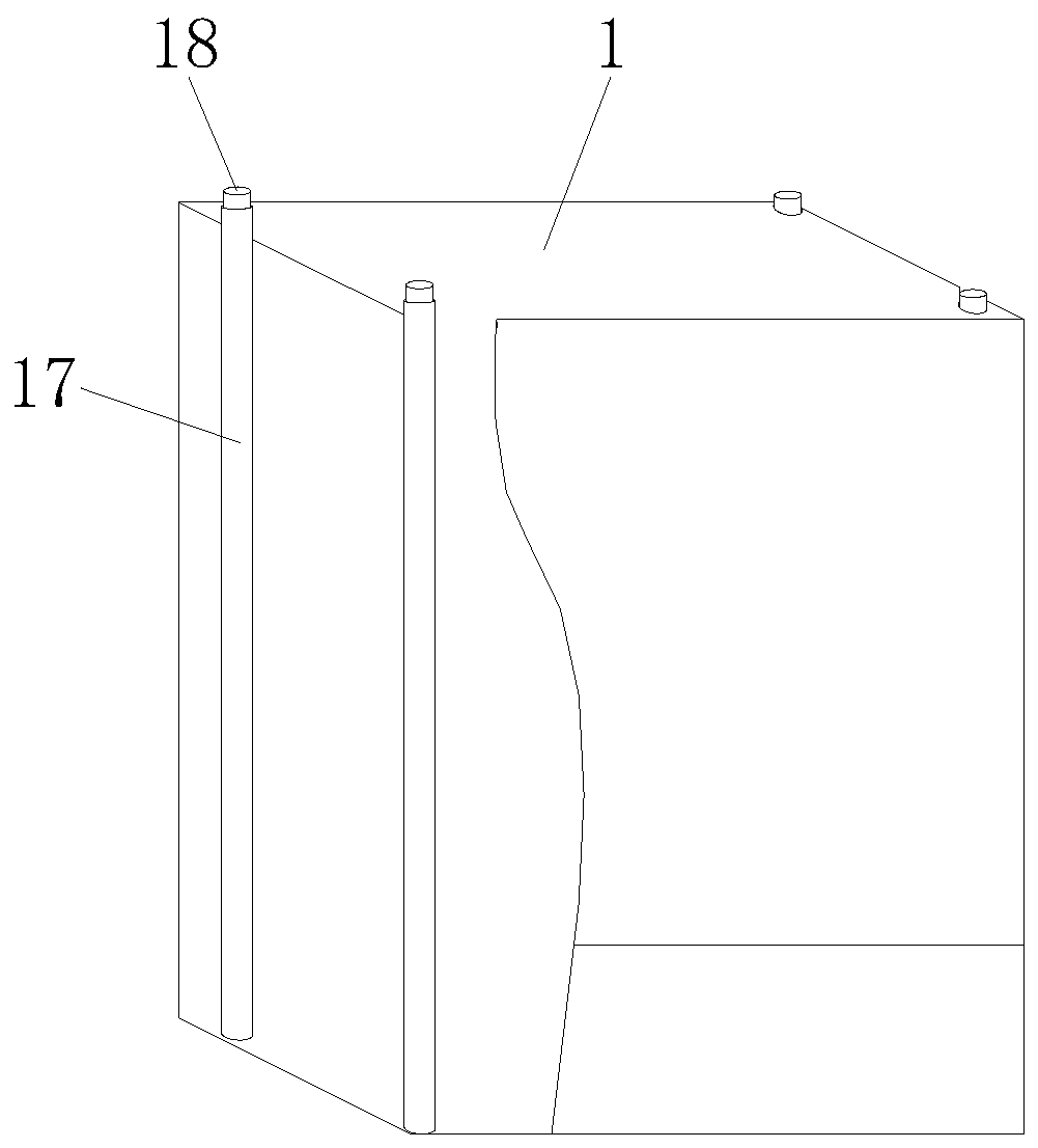
[0020] See Figure 1-4 , The present invention provides a technical solution: a water pump self-floating waterproof control cabinet, comprising a cabinet body 1, the bottom plate of the cabinet body 1 is fixedly connected with a buoyancy bracket 2, and the left opening of the cabinet body 1 is hinged with a left opening door 3 , The outer surface of the left unpacking door 3 is fixedly connected with a left-opening hollow handle 4, and t...


PUM


Abstract

The invention discloses a water pump self-floating waterproof control cabinet. The cabinet comprises a cabinet body, a buoyancy bracket is fixedly connected to a bottom plate of the cabinet body. A left opening box door is hinged to the left side of the cabinet body; a left opening hollow handle is fixedly connected to the outer surface of the left opening box door; the outer surface of the left box opening door is fixedly connected with a control panel; an alarm lamp is fixedly connected to the lower portion of the control panel, the outer surface of the left box opening door is fixedly connected with a lock grid inserting box and a cabinet door lock grid inserting rod, a right box opening door is arranged on the side, symmetrical along the center line of the cabinet body, of the left boxopening door, and one opening of the right box opening door is hinged to a right opening of the cabinet body. A cabinet body permeable self-floating waterproof mode is adopted, so that the cabinet body slowly climbs upwards along the guide rod along with rising of the liquid level and sends out a permeable alarm instruction, the submerging time of the cabinet body is prolonged, sufficient exclusion and repair time is reserved for maintenance personnel, and the problem of permeable submerging of a buried pump station and a basement is solved.

Description

Technical field [0001] The invention relates to the technical field of water pump waterproof cabinet making, in particular to a water pump self-floating waterproof control cabinet. Background technique [0002] With the rapid development of my country’s construction industry and the advancement of sponge city construction projects, people’s requirements for the natural environment are increasing day by day. Many building equipment pump rooms and control systems are laid below frozen soil or arranged underground, which saves land resources. It also beautifies the environment. The biggest trouble in underground equipment, the control cabinet system has a low potential and is easily affected by pool seepage, surface water, and flooding. In the case of pump room flooding accidents, the control cabinet is likely to be immersed in water, leading to damage to control components. The fire pump cannot be guaranteed to start and run reliably, maintenance is relatively cumbersome and the tr...

Claims


Application Information

Patent Timeline
Patent Type & Authority Applications(China)
IPC IPC(8): H05K5/02H05K5/06F04B49/00
CPCF04B49/00H05K5/0234H05K5/061
Inventor 徐亚华
Owner 江苏富亚给排水科技有限公司
Why Eureka
Try Eureka