
Spent fuel water tank natural ventilation and water recovery system responding to serious accident

A spent fuel pool and natural ventilation technology, applied in ventilation systems, space heating and ventilation, applications, etc., can solve the problems of hydrogen accumulation in fuel plants, condensed water cannot be recycled and reused, hydrogen explosions, etc., and achieve passive characteristics High reliability, extended submersion time, and overheating prevention effects

Active Publication Date: 2014-06-18
CHINA NUCLEAR POWER ENG CO LTD
View PDF2 Cites 0 Cited by
  • Summary
  • Abstract
  • Description
  • Claims
  • Application Information

AI Technical Summary

Problems solved by technology

Under accident conditions, the boiling of the spent fuel pool and the lack of ventilation in the building will bring many adverse consequences: first, the steam generated by the boiling of the spent fuel pool will fill the entire fuel building, and then pass through the pressure boundaries of various places as the pressure of the building increases. Unpredictable spills occur, and these vapors will eventually condense everywhere in the nuclear island to cause cross-radiation contamination; secondly, the condensed water that overflows, condenses, and spreads around the nuclear island cannot usually be recycled; in addition, as As the accident progresses, once the fuel assembly melts down and hydrogen is released, the fuel plant that is relatively closed but has no hydrogen elimination facilities is very likely to have hydrogen accumulation, followed by a hydrogen explosion

Method used


Image

  • Spent fuel water tank natural ventilation and water recovery system responding to serious accident
  • Spent fuel water tank natural ventilation and water recovery system responding to serious accident
  • Spent fuel water tank natural ventilation and water recovery system responding to serious accident

Examples


Embodiment Construction

[0021] The present invention will be further described in detail below in conjunction with the accompanying drawings and specific embodiments.

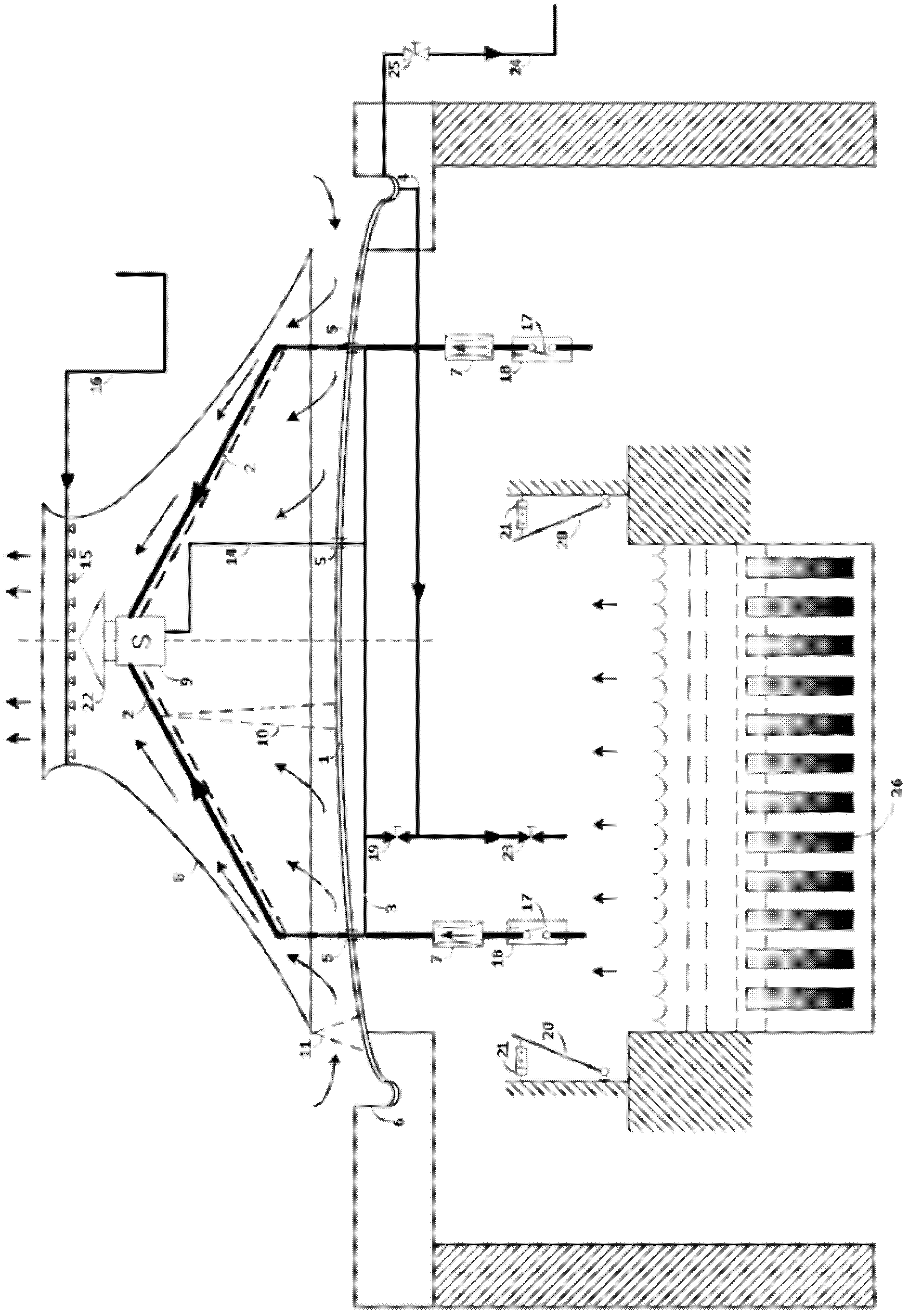
[0022] Such as figure 1 As shown, the natural ventilation and water recovery system of the spent fuel pool for severe accidents includes a metal dome 1 as a part of the roof of the fuel plant. The metal dome 1 has a plurality of ventilation channels 2 for natural ventilation of the spent fuel pool in severe accidents. A natural ventilation chimney 8 is arranged above the whole of the plurality of ventilation channels 2. The entrance of the ventilation channel 2 is located above the spent fuel pool where the spent fuel assembly 26 is stored, and the outlet of the ventilation channel 2 is connected to the water eliminator 9. An atomizing sprinkler 15 is provided between the outlet of the water eliminator 9 and the exhaust port of the water eliminator 9. The atomizing sprinkler 15 is connected to the spray water supply pipeline 16 arrang...


PUM


Abstract

The invention belongs to design of a fuel building ventilating system for a nuclear power station and in particular relates to a spent fuel water tank natural ventilation and water recovery system responding to a serious accident. The structure of the system comprises a metal dome which is taken as one part of roof of a fuel building, wherein the metal dome is provided with a plurality of ventilation channels in circumferential direction; a natural ventilation chimney is arranged above the ventilation channels; the inlet of each ventilation channel is arranged above a spent fuel water tank; and the outlet of each ventilation channel is connected with a water receiver. According to the invention, the natural ventilation on a building in which the spent fuel water tank is located under the serious accident condition and discharge of decay heat of partial spent fuel are realized by multiple ventilation channels on the roof of the fuel building, thus the fuel building is prevented from being overheated and overpressured and hydrogen is prevented from gathering; and isolating, triggering and main functions of the spent fuel water tank natural ventilation and water recovery system disclosed by the invention are not dependent on exterior power input, thus the spent fuel water tank natural ventilation and water recovery system disclosed by the invention has non-active characteristic and high reliability.

Description

technical field [0001] The invention belongs to the design of the ventilation system of a nuclear power plant fuel building, and in particular relates to a natural ventilation and water recovery system for spent fuel pools for serious accidents. Background technique [0002] For the second-generation (M310) and third-generation (AP1000) nuclear power units, the design of the existing spent fuel pool ventilation system (nuclear fuel plant ventilation system) mainly considers three aspects: 1. To ensure the safe and normal operation of relevant equipment and personnel in the fuel plant Enter the required indoor temperature; 2. Limit the water vapor content in the indoor ambient air of the fuel plant to reduce the risk of condensation on the wall of the fuel pool; 3. In the event of fuel loading and unloading accidents, lead tank loading and unloading accidents, and LOCA accidents, reduce Remove airborne radioactivity to acceptable levels. It can be seen that the design of the...

Claims


Application Information

Patent Timeline
Patent Type & Authority Patents(China)
IPC IPC(8): F24F7/04G21C15/18
CPCY02E30/40Y02E30/30
Inventor 韩旭李军李博郑忠良
Owner CHINA NUCLEAR POWER ENG CO LTD
Learn More