
Electrical control cabinet with push-pull mounting plate

A kind of technology of electrical control cabinet and installation board

Inactive Publication Date: 2020-03-31
TAICANG DENASEN MECHANICAL & ELECTRICAL ENG CO LTD
View PDF0 Cites 0 Cited by
  • Summary
  • Abstract
  • Description
  • Claims
  • Application Information

AI Technical Summary

Problems solved by technology

[0003] The installation boards of traditional electrical control cabinets are relatively close to the inner side of the cabinet body. Due to space constraints in some utility poles or relatively crowded corridors, it is difficult for wiring personnel to carry out wiring, and the installation boards are close to the inner side of the cabinet body, resulting in the installation holes. The distance between the cabinets is very close, it is difficult for wiring personnel to install bolts to fix the lines, resulting in inaccurate circuit layout, and the traditional cabinets are generally fully enclosed, which is not easy to dissipate heat, which may cause the circuit to become hot and affect the safety of the circuit

Method used


Image

  • Electrical control cabinet with push-pull mounting plate
  • Electrical control cabinet with push-pull mounting plate
  • Electrical control cabinet with push-pull mounting plate

Examples


Embodiment Construction

[0022] The present invention will be further described in detail below in conjunction with the accompanying drawings and specific embodiments.

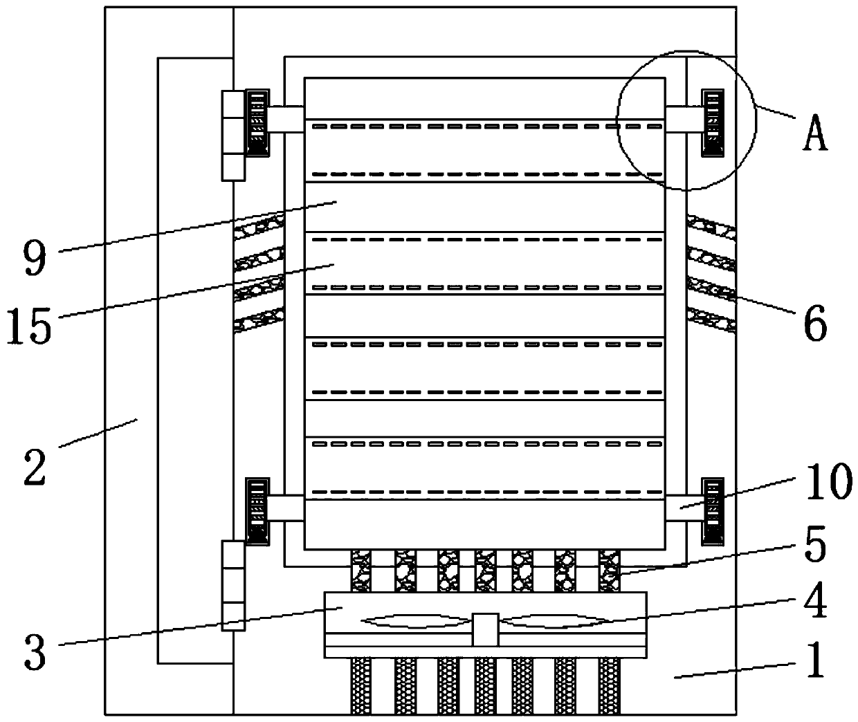
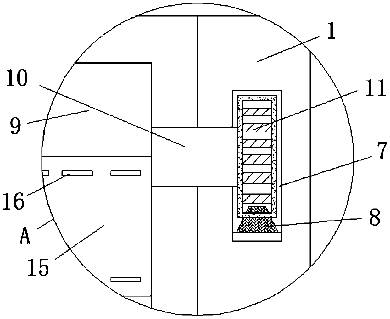
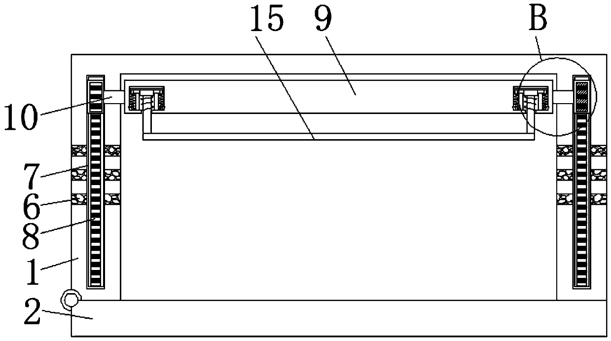
[0023] as attached Figure 1-4 The shown electrical control cabinet with a push-pull mounting plate according to the present invention includes a cabinet body 1, the cabinet body 1 is set as a cabinet body with an inner cavity, and the side wall of the cabinet body 1 is hinged with a side door 2 through a hinge. , the lower end wall of the cabinet body 1 is provided with an air slot 3, the air slot 3 is set as a circular slot, and the fan 4 is fixedly connected to the air slot 3. The model of the fan 4 is W2E200-HK38-01, and the wind is blown into the Heat dissipation is carried out in the cabinet body 1, and the upper and lower walls of the air duct 3 are provided with air inlet holes 5 penetrating the lower wall of the cabinet body 1. There are multiple air inlet holes 5, and the air inlet holes 5 are divided into upper air inlets a...


PUM


Abstract

The invention relates to an electrical control cabinet with a push-pull mounting plate. The cabinet comprises a cabinet body, a side door is hinged to the side wall of the cabinet body through a hinge. An air groove is formed in the lower end wall of the cabinet body; a fan is fixedly connected in the air groove; air inlet holes penetrating through the lower wall of the cabinet body are formed inthe upper and lower walls of the air groove; the side wall of the cabinet body is provided with a plurality of air outlet holes which are uniformly distributed. The inner wall of the cabinet body is provided with a plurality of uniformly symmetrical first slideways; the inner wall of the lower end of the first slideway is fixedly connected with a gear plate; the first slide way is movably connected with a pull plate through a rotating shaft; and a rotating wheel is movably connected to the end, located in the first sliding way, of the rotating shaft, the rotating wheel is engaged with the gearplate, technicians can conveniently and accurately conduct wiring. Meanwhile, heat dissipation is conducted on the electrical control cabinet, water vapor and the like are prevented from entering theelectrical control cabinet to influence the safety of a circuit in the electrical control cabinet, and the device is convenient to use.

Description

technical field [0001] The invention relates to the field of control cabinets, in particular to an electrical control cabinet with a push-pull mounting plate. Background technique [0002] The control cabinet is to assemble the switchgear, measuring instrument, protective device and auxiliary equipment in the closed or semiclosed metal cabinet or on the screen width according to the requirements of electrical wiring. and the safety of surrounding equipment. [0003] The installation boards of traditional electrical control cabinets are relatively close to the inner side of the cabinet body. Due to space constraints in some utility poles or relatively crowded corridors, it is difficult for wiring personnel to carry out wiring, and the installation boards are close to the inner side of the cabinet body, resulting in the installation holes. The distance between the cabinets is very close, and it is difficult for wiring personnel to install bolts to fix the lines, resulting in ...

Claims


Application Information

Patent Timeline
IPC IPC(8): H05K7/14H05K7/20H05K5/02
CPCH05K5/0213H05K7/1401H05K7/1418H05K7/20136H05K7/20172
Inventor 倪晔波冯广周
Owner TAICANG DENASEN MECHANICAL & ELECTRICAL ENG CO LTD
Learn More