Wire bonding device

A wire bonding device and wire bonding technology, which are applied in the manufacturing of electrical components, electrical solid-state devices, semiconductor/solid-state devices, etc., can solve problems such as poor electrode connection and achieve the effect of improving workability

Pending Publication Date: 2020-03-31
SHINKAWA CO LTD
View PDF8 Cites 0 Cited by
  • Summary
  • Abstract
  • Description
  • Claims
  • Application Information

AI Technical Summary

Problems solved by technology

Oxidation of the airless balloon may be the cause of a poor connection to the electrode

Method used


Image

  • Wire bonding device
  • Wire bonding device
  • Wire bonding device

Examples


Embodiment Construction

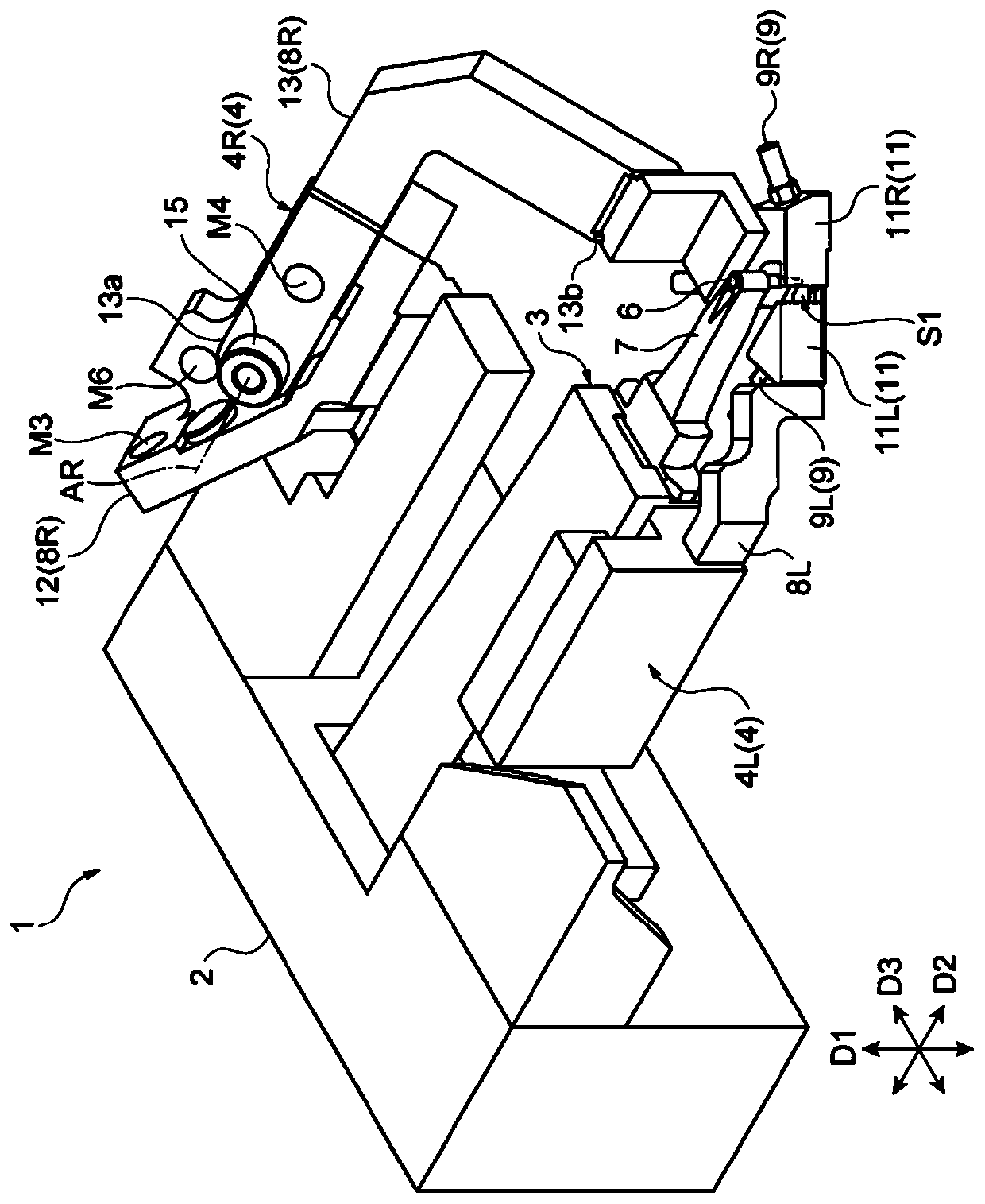
[0022] Below, refer to the attached Figure 1 The method for implementing the present invention will be described in detail. In the description of the drawings, the same components are assigned the same symbols, and repeated descriptions are omitted.

[0023] figure 1 The wire bonding apparatus 1 shown in will bond wires to electrodes of semiconductor chips or substrates. The wire bonding device 1 has a base unit 2 (base portion), a capillary unit 3 , and a chamber unit 4 . In addition, although the wire bonding apparatus 1 has other components, such as a housing|casing, a control device, and a feeder, these components are abbreviate|omitted in the following description and drawing.

[0024] The wire bonding device 1 holds wires so as to protrude slightly from the capillary unit 3 . In the holding state, a free air ball (Free Air Ball) is formed at the tip of the protruding bonding wire. Next, the wire bonding apparatus 1 performs ball bonding. Specifically, the capillar...


PUM


Abstract

A wire bonding device 1 is provided with a capillary 6, and a chamber unit 4 that forms an inert gas region S1 in an area around the capillary 6. The chamber unit 4 has: a right chamber block 11R; a left chamber block 11L; and a movable mechanism 15 that relatively moves the right chamber block 11R with respect to the capillary 6. The movable mechanism 15 performs alternate switching between: first mode, in which the area around the capillary 6 is surrounded by the right chamber block 11R and the left chamber block 11L; and second mode, in which a part of the area around the capillary 6 is opened by moving the right chamber block 11R.

Description

technical field [0001] The invention relates to a wire bonding device. Background technique [0002] When bonding wires to electrodes of a semiconductor chip, ball bonding is performed. In ball bonding, first, the tip of the bonding wire protruding from the tip of the capillary is melted. Free air balls are formed by the melting. Next, press the air-free balloon against the electrodes. Airless balloons are molten metal, so they oxidize more easily. Oxidation of the airless balloon may be the cause of poor connection to the electrodes. [0003] prior art literature [0004] patent documents [0005] Patent Document 1: Japanese Patent Laid-Open No. 2007-294975 [0006] Patent Document 2: Specification of US Patent Application Publication No. 2007 / 0251980 Contents of the invention [0007] The problem to be solved by the invention [0008] For example, Patent Document 1 and Patent Document 2 disclose techniques for suppressing oxidation of airless balloons. In this ...

Claims


Application Information

Patent Timeline
IPC IPC(8): H01L21/60
CPCH01L2224/781H01L24/78H01L2224/48463H01L2224/78H01L2224/85075
Inventor 小作贵义
Owner SHINKAWA CO LTD
Why Eureka
Try Eureka