
Construction method for plugging construction joint of frame beam

A construction method and technology for frame beams, applied in joists, girders, truss beams, etc., can solve the problems of frame beam concrete running, cement slurry seepage, hemp surface, etc., to avoid concrete slag inclusion, easy installation and dismantling, Good joint quality effect

Active Publication Date: 2017-01-18
CHINA CONSTR SIXTH ENG BUREAU CIVILENG +1
View PDF6 Cites 4 Cited by
  • Summary
  • Abstract
  • Description
  • Claims
  • Application Information

AI Technical Summary

Problems solved by technology

[0012] 2.1 Concrete running slurry
[0013] Since the dense-mesh barbed wire or the quick-easy closing net are all porous structures, the cement slurry will inevitably seep out during the concrete pouring of the frame beam, resulting in the leakage and pitting of the frame beam concrete at the contact part with the dense-mesh barbed wire or the quick-easy closing net Phenomenon that affects the overall quality of concrete
[0014] 2. 2 Affect the joint strength of concrete at construction joints

Method used


Image

  • Construction method for plugging construction joint of frame beam
  • Construction method for plugging construction joint of frame beam
  • Construction method for plugging construction joint of frame beam

Examples


Embodiment 1

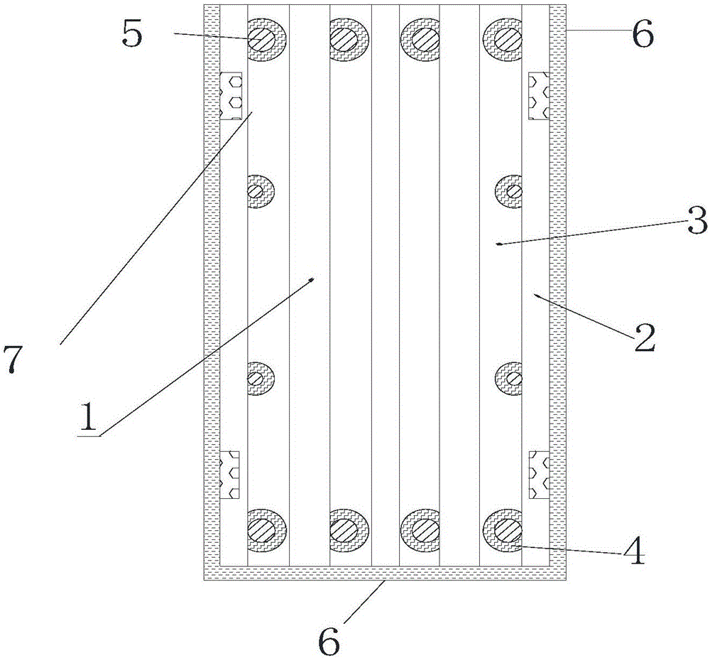
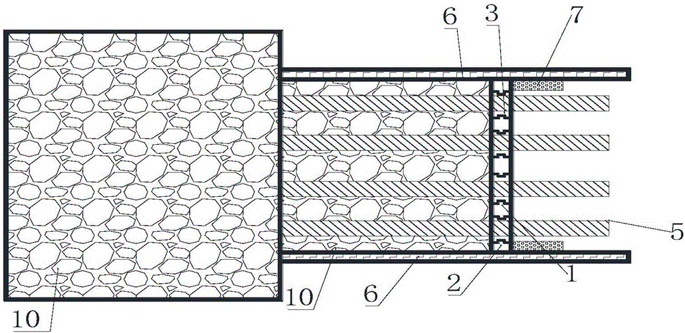
[0050] (1) U-shaped frame beam template 6 is installed at the construction joint position;

[0051](2) Positioning stoppers 7 are respectively installed up and down on the insides of the front ends of the two vertical plates of the frame beam formwork;

[0052] (3) Install the full-length longitudinal reinforcement 5 of multiple beams in the frame beam formwork;

[0053] (4) Insert the side of the plugging steel formwork 3 with a full-length groove along the frame beam longitudinal reinforcement 5 direction between every two adjacent longitudinal reinforcements 5, and the full-length grooves are respectively opened along the vertical direction. In the middle of the left wall and the right wall of each blocking steel formwork 3, there is a C-shaped opening corresponding to the position of the longitudinal reinforcement 5 on the left wall or the right wall of the blocking steel formwork 3, and the opening A rubber ring 4 is installed inside, and the inner ring diameter of the r...

Embodiment 2

[0062] (1) U-shaped frame beam template 6 is installed at the construction joint position;

[0063] (2) Positioning stoppers 7 are respectively installed up and down on the insides of the front ends of the two vertical plates of the frame beam formwork;

[0064] (3) Install the full-length longitudinal reinforcement 5 of multiple beams in the frame beam formwork;

[0065] (4) Insert the side of the plugging steel formwork 3 with a full-length groove along the frame beam longitudinal reinforcement 5 direction between every two adjacent longitudinal reinforcements 5, and the full-length grooves are respectively opened along the vertical direction. In the middle of the left wall and the right wall of each blocking steel formwork 3, there is a C-shaped opening corresponding to the position of the longitudinal reinforcement 5 on the left wall or the right wall of the blocking steel formwork 3, and the opening A rubber ring 4 is installed inside, and the diameter of the inner ring ...

Embodiment 3

[0074] (1) U-shaped frame beam template 6 is installed at the construction joint position;

[0075] (2) Positioning stoppers 7 are respectively installed up and down on the insides of the front ends of the two vertical plates of the frame beam formwork;

[0076] (3) Install the full-length longitudinal reinforcement 5 of multiple beams in the frame beam formwork;

[0077] (4) Insert the side of the plugging steel formwork 3 with a full-length groove along the frame beam longitudinal reinforcement 5 direction between every two adjacent longitudinal reinforcements 5, and the full-length grooves are respectively opened along the vertical direction. In the middle of the left wall and the right wall of each blocking steel formwork 3, there is a C-shaped opening corresponding to the position of the longitudinal reinforcement 5 on the left wall or the right wall of the blocking steel formwork 3, and the opening A rubber ring 4 is installed inside, and the inner ring diameter of the ...


PUM


Abstract

The invention discloses a construction method for plugging a construction joint of a frame beam. The construction method comprises the following steps: mounting a u-shaped frame beam formwork at the construction joint; mounting positioning baffle blocks at upper and lower parts of the inner sides of the front ends of two vertical plates of the frame beam formwork respectively; mounting a plurality of longitudinal through beam steel bars inside the frame beam formwork; through occlusion of grooves for plugging steel frameworks and lug bosses for connecting steel frameworks and end steel frameworks, forming a combined framework, wherein the combined framework and the frame beam formwork are equal in height; adjusting the combined framework so as to tightly press the combined framework against the positioning baffle blocks. A frame beam concrete structure built with the construction method is compact inside and smooth outside, and slag inclusion, a pitted surface and grout runout of concrete are avoided; meanwhile, the jointing quality of concrete poured in the first time and concrete poured in the second time is good, the steel frameworks are overturned for many times and are conveniently mounted and dismounted, and the construction method has the characteristics of environment friendliness, energy conservation, economy and practicality.

Description

technical field [0001] The invention relates to a construction method for sealing construction joints of frame beams, which is suitable for sealing the construction joints of frame beams of reinforced concrete structures by pouring concrete in stages. Background technique [0002] In the context of the continuous development of large and high single buildings today, the length and width of the building are becoming larger and larger. In order to solve the cracks caused by the structure itself due to the overlength and the reasonable construction process flow requirements, the concrete floor structure A certain number of construction joints will be left in the length and width directions according to the design specifications and construction needs. The construction joints at the position of the frame beams need to be made as straight joints perpendicular to the length direction of the frame beams according to the specifications, and the sealing of the construction joints beco...

Claims


Application Information

Patent Timeline
Patent Type & Authority Applications(China)
IPC IPC(8): E04C3/20E04G13/04
CPCE04C3/20E04G13/04
Inventor 郭建东袁银书张振禹李鹏钟成新
Owner CHINA CONSTR SIXTH ENG BUREAU CIVILENG
Learn More