
Efficient welding method for one side welding both-side formation

A single-sided welding double-sided, welding method technology, applied in welding equipment, welding accessories, arc welding equipment and other directions, can solve the problems of small angle welding difficult to reach, low efficiency of manual arc welding, welding tools and pipe butt , to achieve the effect of reducing welding wettability, excellent arc starting characteristics, and shortening the training period

Inactive Publication Date: 2020-11-13
厦门天吴海洋科技有限公司 +1
View PDF4 Cites 2 Cited by
  • Summary
  • Abstract
  • Description
  • Claims
  • Application Information

AI Technical Summary

Problems solved by technology

[0003] Various traditional welding methods are difficult to meet the requirements. The dihedral angle of some YKY nodes is as small as 30°. If the dihedral angle is too small, the welding tool will collide with the pipe and the welding will be interrupted.
[0004] The traditional TKY node welding mostly adopts the "two-step method". The root single-sided welding and double-sided forming welding methods include manual arc welding (SMAW) and argon tungsten arc welding (GTAW). high-quality forming, but its welding efficiency is low, and the extension length of the tungsten electrode is limited, and it is difficult to weld at small angles. Welding is prone to slag inclusion and is not easy to remove; manual arc welding (SMAW) and flux-cored wire welding (FCAW-G) are mostly used for the filling cover. Manual arc welding is less efficient, and flux-cored wire welding is prone to slag inclusion and cannot be automatically Welding, and cannot achieve continuous operation

Method used


Image

  • Efficient welding method for one side welding both-side formation

Examples


Embodiment Construction

[0030] In order to better explain the present invention and facilitate understanding, the present invention will be described in detail below through specific embodiments in conjunction with the accompanying drawings.

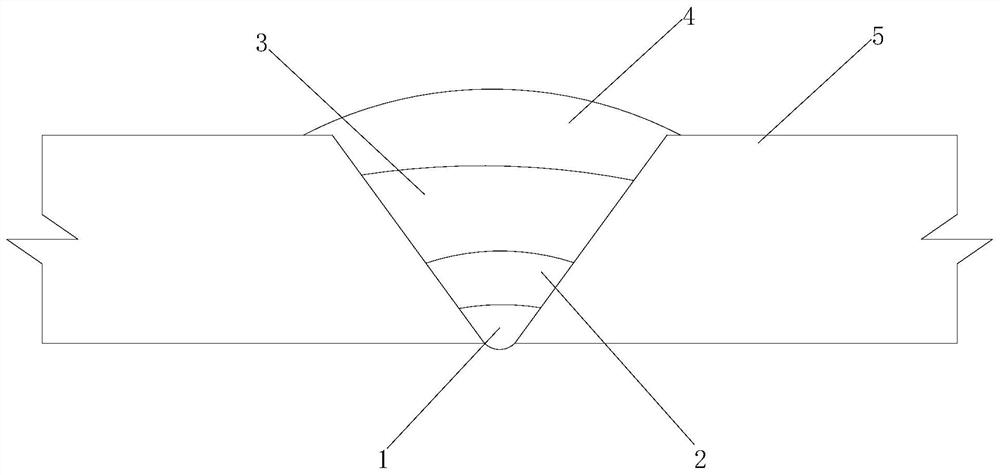
[0031] A welding method for high-efficiency single-sided welding and double-sided molding according to an embodiment of the present invention, such as figure 1 As shown, the specific steps are as follows:

[0032] Step S1, blanking the workpiece according to the drawing requirements;

[0033] Step S2, grinding and assembling the blanked workpiece according to the drawing to form the workpiece 5 to be welded;

[0034] Step S3, start the digital pulse arc welding machine, select the pulse arc mode on the digital pulse arc welding machine, adjust the current to 60-100A, and complete the welding of the root bead 1 of the workpiece to be welded. The thickness of the root bead 1 is 4-8mm , the width of the root bead 1 is 4-8mm, and this layer of bead is mainly used...


PUM

PropertyMeasurementUnit
thicknessaaaaaaaaaa
widthaaaaaaaaaa
widthaaaaaaaaaa

Abstract

The invention relates to an efficient welding method for one side welding both-side formation. The details of the efficient welding method are as follows: workpiece blanking is carried out; a workpiece after blanking is polished and assembled to form a workpiece to be welded; a digital pulse electric arc welder selects a pulse electric arc mode and completes root pass welding of the workpiece to be welded; then, the digital pulse electric arc welder selects a spray electric arc mode and completes hot weld layer root pass welding of the workpiece to be welded; after hot weld layer root pass welding is completed, the digital pulse electric arc welder selects the spray electric arc mode and completes filling root pass welding of the workpiece to be welded; after filling root pass welding is completed, the digital pulse electric arc welder selects the spray electric arc mode and completes capping root pass welding of the workpiece to be welded; and after welding is over, a power supply isturned off. The efficient welding method can realize one side welding both-side formation, has the advantages of high cladding efficiency and good operability, and solves the technical problems that one side welding both-side formation of traditional TKY welding joints is not high in welding quality, low in operation efficiency and incapable of realizing continuous operation.

Description

technical field [0001] The invention relates to the field of welding methods, in particular to a welding method for high-efficiency single-side welding and double-side forming. Background technique [0002] Tube truss structure, also known as steel tube truss structure, tube truss or tube structure, is a form of steel structure composed of tubular cross-sectional members. There are a large number of TKY joints in the pipe truss structure, and the welding position of TKY joints changes along the intersecting line, which is a severe test for the welding skills of welders. According to AWS regulations, welders engaged in welding TYK joints of pipes must obtain 6GR that meets the requirements of this code. Welder qualification certificate; the support frame pipe is a closed structure, and its TYK joints can only be welded from the outside of the pipe. In order to ensure the full penetration of the TYK joints, the welding process adopted for the root weld pass requires single-sid...

Claims


Application Information

Patent Timeline
Patent Type & Authority Applications(China)
IPC IPC(8): B23K9/09B23K9/235B23K9/32B23K33/00
CPCB23K9/09B23K9/235B23K9/32B23K33/00
Inventor 陈增铎肖明颖范振红
Owner 厦门天吴海洋科技有限公司
Learn More