
A protection device for climbing a tower based on an unmanned aerial vehicle platform

A protection device, drone technology, applied in the direction of climbing, sports accessories, etc., can solve problems such as safety hazards

Active Publication Date: 2021-05-04
国网河南省电力公司超高压公司 +1
View PDF7 Cites 0 Cited by
  • Summary
  • Abstract
  • Description
  • Claims
  • Application Information

AI Technical Summary

Problems solved by technology

However, the utility model must exchange seat belts when passing through the iron tower nodes, which has great potential safety hazards

Method used


Image

  • A protection device for climbing a tower based on an unmanned aerial vehicle platform
  • A protection device for climbing a tower based on an unmanned aerial vehicle platform
  • A protection device for climbing a tower based on an unmanned aerial vehicle platform

Examples


Embodiment 1

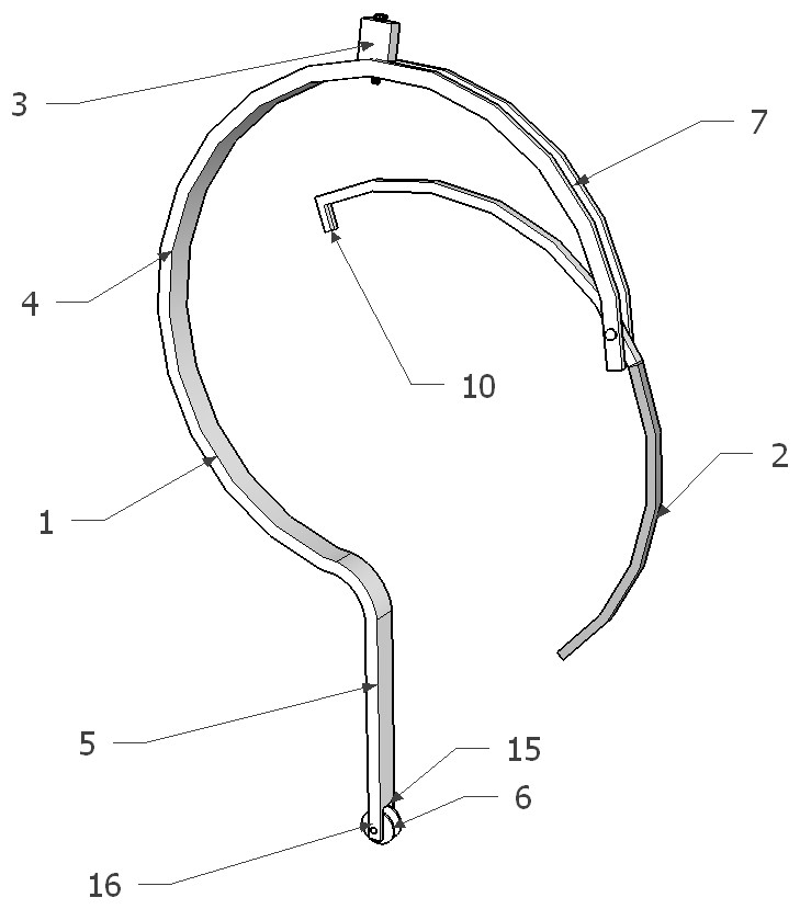
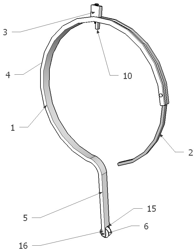
[0049]Such asFigure 1-6As shown, a climb protection device based on a drone platform, including a hanging ring 1, a closed rod 2, and an automatic lock 3.

[0050]The hanging ring 1 includes a C-shaped annular sleeve 4 and the lower end of the annular sleeve 4, and the neck 5 integrally formed with the annular sleeve 4, the neck 5 is provided with a pulley 6; the neck 5 bottom end hollow set the wheel groove 15 The wheel groove 15 is provided as a tall plate 16, and the pulley 6 is disposed in the wheel groove 15, and the pulley 6 is connected to the ear plate 16 through the pin shaft. The ear plate 16 and the neck 5 are integrated structures, safe and secure, and the slit between the pulley 6 and the ear plate 16 is very small, preventing the safety rope jumper, and the card line during use.

[0051]The shape of the closed rod 2 is a C-shaped structure, in reverse the opening direction, the end portion of the closed rod 2 and the annular sleeve 4, and the end portion of the annular sleev...

Embodiment 2

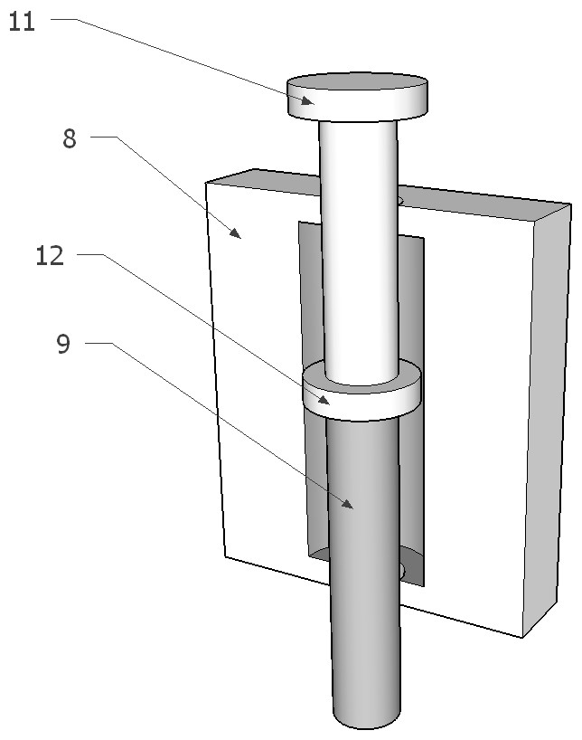
[0063]Such asFigure 7 As shown, the structure of the present embodiment and the embodiment is substantially the same, and the difference is that the lock column 9 is a conical body structure, and the lower portion diameter of the lock column 9 is larger than the upper diameter, and the upper portion of the lock column 9 is provided with a cylindrical column head 11, the lock shell. 8 Internally disposed a conical through hole corresponding to the shape of the lock column 9. The conical body structure can only achieve the upper and lower slides of the lock column 9 in the through hole of the lock case 8, and the lower diameter is larger than the sliding range of the lock column 9, preventing the lock post 9 from over-slip. The lock case 8, the cylindrical pillar 11 prevents the locking column 9 from being detached from the lower portion.

Embodiment 3

[0065]Such asFigure 8 As shown, the structure of the present embodiment and the embodiment is substantially the same, and the difference is that the hook ring groove 13 is provided at the top of the lock post 9, and the hook loop 14 is disposed in the hook loop 14. The hook ring 14 is more convenient to connect with the drone hindle, and realizes that the drone automatically lifts the lock column 9, and then removes the climb protection device.


PUM


Abstract

The invention discloses a tower climbing protection device based on an unmanned aerial vehicle platform, which includes a hanging ring, a closing rod and an automatic lock; the hanging ring includes a C-shaped annular sleeve and a neck integrally formed with the annular sleeve at the lower end of the annular sleeve. The bottom end of the neck is provided with a pulley; the closing rod is a C-shaped structure opposite to the opening direction of the annular sleeve, the closing rod and the end of the annular sleeve are rotatably connected, the end of the annular sleeve is provided with a strip groove, and the upper part of the closing rod It is arranged in a bar-shaped groove; an automatic lock is arranged on the top of the hanging ring, and the automatic lock includes a lock case and a lock column that can slide up and down in the lock case. The invention can use the unmanned aerial vehicle to hang the closed hook on the pole tower, connect the rope with the climbing pole tower personnel, and realize the continuous personal protection function of the high-altitude personnel. The structure is simple, time-saving and labor-saving, and the safety is high.

Description

Technical field[0001]The present invention relates to an ascending operation safety protection tool, in particular, to a counterturial protection device based on a drone platform.Background technique[0002]Development of power industry of our country is booming, with the growth of electricity consumption in the national economy is growing significantly, with the development of electric power industry, the need for ultra-high pressure long-distance power transmission, long-distance power transmission during the time, the most common way a high-pressure delivery line is suspended by transmission erected, the erection of these floating high voltage transmission line connected often through the high pressure transmission tower mounted, the distance from the ground and the high span relatively large, while the high voltage transmission lines are often in outdoor open state Under operation, it is extremely vulnerable to natural environmental erosion and damage, so in order to ensure the sa...

Claims


Application Information

Patent Timeline
IPC IPC(8): A63B27/00
CPCA63B27/00
Inventor 李雪奎高昆鹏刘琦杨东辉刘阔赵龙李瑞鹏韩旭马志靳航兰帅峰李忠民张建辉陶留海张利
Owner 国网河南省电力公司超高压公司
Learn More