Distributor for film evaporators

A thin film evaporator and evaporator technology, applied in evaporator accessories, evaporation, chemical instruments and methods, etc., can solve problems such as unfavorable foam elimination, affecting evaporation quality, affecting material evaporation, etc., to ensure evaporation effect and ensure evaporation quality. , the effect of improving evaporation efficiency

Active Publication Date: 2020-04-03
台州恒裕科技有限公司
View PDF12 Cites 1 Cited by
  • Summary
  • Abstract
  • Description
  • Claims
  • Application Information

AI Technical Summary

Problems solved by technology

[0004] However, when the existing distributor for the thin film evaporator is in use, since the material in the feeding pipe 3 is fed into the evaporator 2 by a certain pushing pressure, under the action of the thrust, the material contacts the rotating distributing pipe 1 and the convex plate 8 The kinetic energy is relatively large, so after being affected by the distribution pipe 1 and the convex plate 8, the rebound force increases when it is turned to the inner wall of the evaporator 2, which will easily cause part of the rebounded material to flow out with the steam, which will affect the evaporation quality. Moreover, when the evaporator When there is a lot of steam in 2, due to the gap between the distribution pipe 1 and the inner wall of the evaporator 2, the steam can easily flow through the gap and directly act on the material that has just entered, or the distribution pipe 1 absorbs the heat of the steam flowing through, so that the material at the distribution pipe 1 Flash evaporation here is not conducive to the elimination of foam and affects the evaporation of subsequent materials along the heating surface

Method used


Image

  • Distributor for film evaporators
  • Distributor for film evaporators
  • Distributor for film evaporators

Examples


Embodiment Construction

[0016] The following will clearly and completely describe the technical solutions in the embodiments of the present invention with reference to the accompanying drawings in the embodiments of the present invention. Obviously, the described embodiments are only some, not all, embodiments of the present invention. Based on the embodiments of the present invention, all other embodiments obtained by persons of ordinary skill in the art without making creative efforts belong to the protection scope of the present invention.

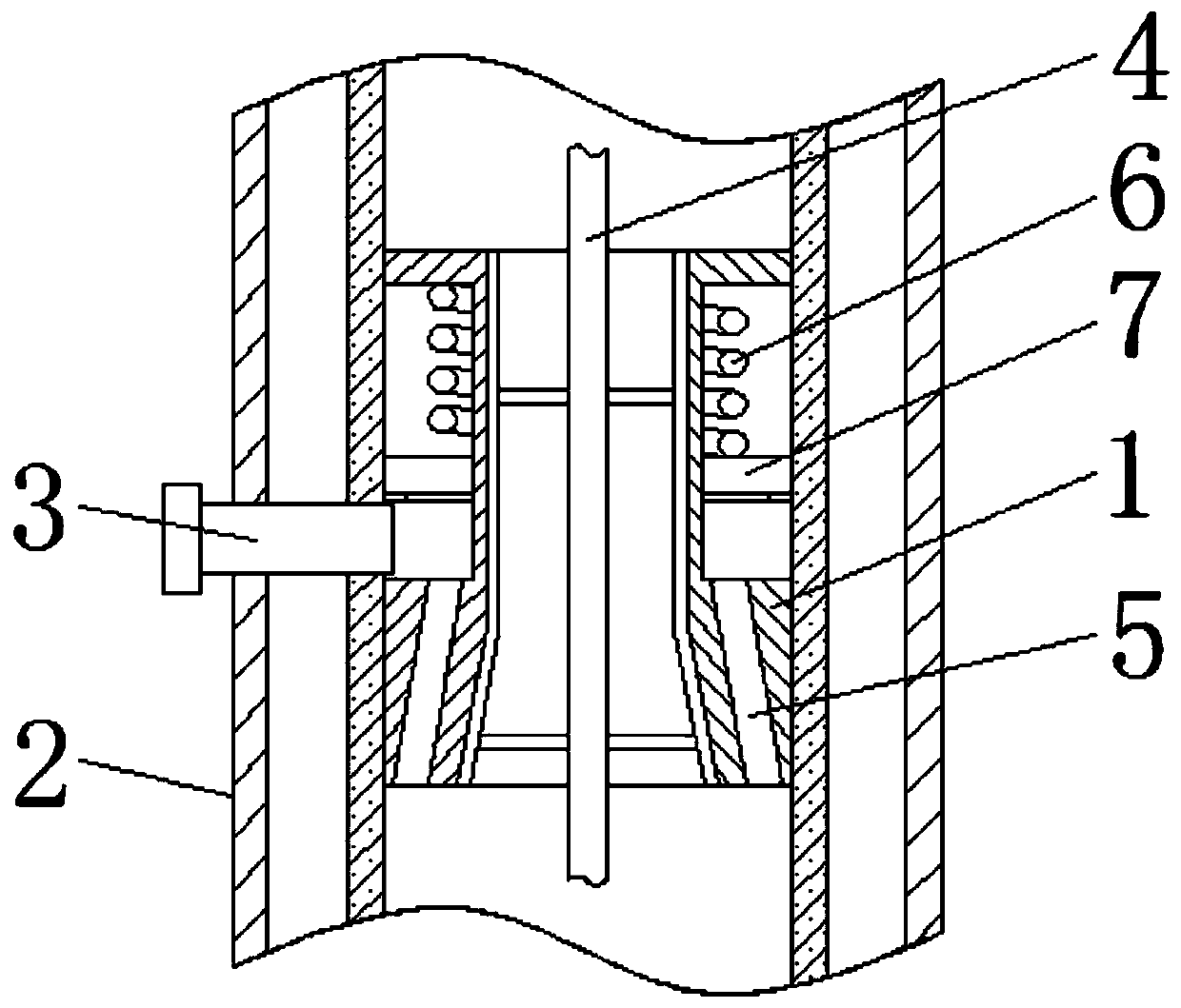
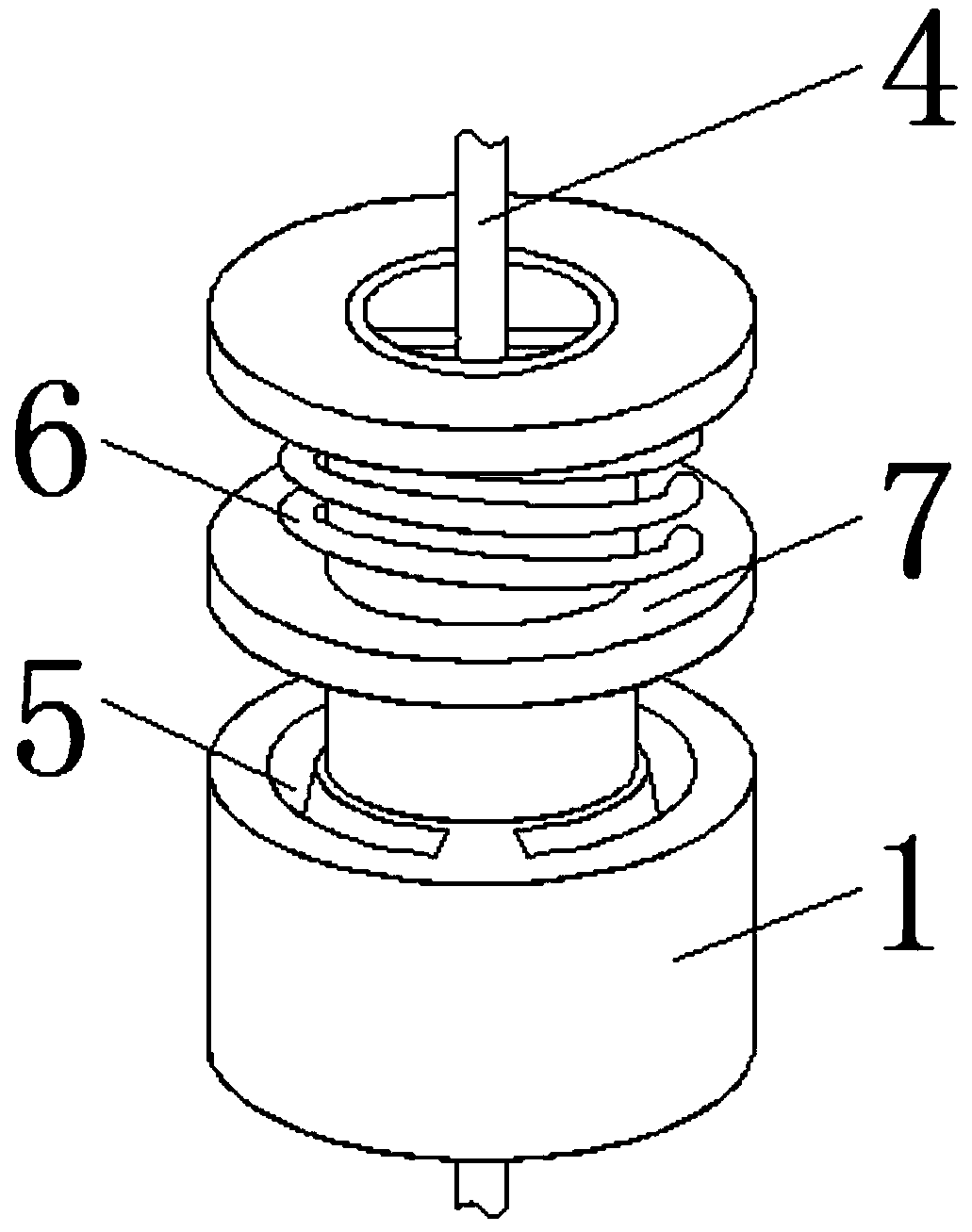
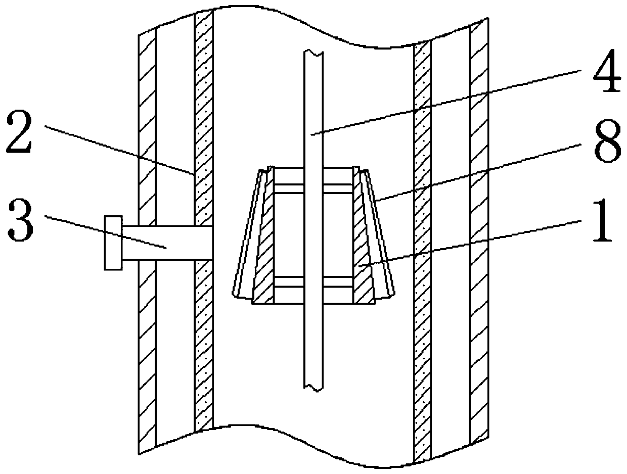
[0017] see Figure 1-2 , a distributor for a thin film evaporator, comprising a distributor tube 1, an evaporator 2, a feed tube 3, and a stirring shaft 4, the distributor tube 1 is movably fitted on the top of the inner cavity of the evaporator 2, and the side of the evaporator 2 is fixedly fitted with a The feeding pipe 3 at the distributing pipe 1, and the middle part of the inner cavity of the evaporator 2 are provided with a stirring shaft 4 that drives t...


PUM


Abstract

The invention relates to the field of film evaporation equipment, and discloses a distributor for film evaporators. The distributor comprises a distributing pipe, an evaporator, a feeding pipe and a stirring rotating shaft, the distributing pipe is movably sleeved at the top of an inner cavity of the evaporator, and the side surface of the evaporator is fixedly sleeved with the feeding pipe positioned at the distributing pipe. According to the distributor for film evaporators disclosed in the invention, the distributing pipe is provided with a groove, the through groove, a spring, and a pistonring are adopted for cooperation, so that materials added into the evaporator through the feeding pipe firstly enter the space of the groove, are uniformly mixed and dispersed, and then uniformly flow to the inner wall of the evaporator through the through groove, so that the materials can be quickly heated by utilizing the evaporator, and the evaporation efficiency is improved; meanwhile, the kinetic energy of the materials entering the groove is converted into the elastic potential energy of the spring, so that when the materials are shifted to the inner wall of the evaporator, the reboundrate of the materials is small, rising steam is effectively prevented from driving part of the materials to move upwards, and the evaporation quality of the materials is guaranteed.

Description

technical field [0001] The invention relates to the field of thin film evaporation equipment, in particular to a distributor for thin film evaporators. Background technique [0002] Thin-film evaporator is a kind of evaporator, which can make the material liquid flow in the form of a film along the wall of the heating tube for heat transfer and evaporation. It has the advantages of high heat transfer efficiency, fast evaporation speed, and short material residence time. Therefore, It is especially suitable for the evaporation of heat-sensitive substances, and has a wide range of applications. Among them, the top of the inner cavity of the thin-film evaporator is usually equipped with a distributor, which evenly pours the material input in the feeding pipe to the inner wall of the evaporator, which is beneficial for the material to accept the heating of the inner wall of the evaporator. [0003] The working principle of the existing thin film evaporator distributor is as foll...

Claims


Application Information

Patent Timeline
Patent Type & Authority Applications(China)
IPC IPC(8): B01D1/22B01D1/30
CPCB01D1/222B01D1/30
Inventor 陈玉平
Owner 台州恒裕科技有限公司
Why Eureka
Try Eureka