Grain dust removing device
A dust removal device and grain technology, which are applied in the directions of solid separation, separation of solids from solids by air flow, chemical instruments and methods, etc., can solve the problems of incomplete removal, inconvenient removal of dust, and insufficient dispersion of grain accumulation. Achieve the effect of high circulation efficiency and high separation efficiency
- Summary
- Abstract
- Description
- Claims
- Application Information
AI Technical Summary
Problems solved by technology
Method used
Image
Examples
Embodiment 1
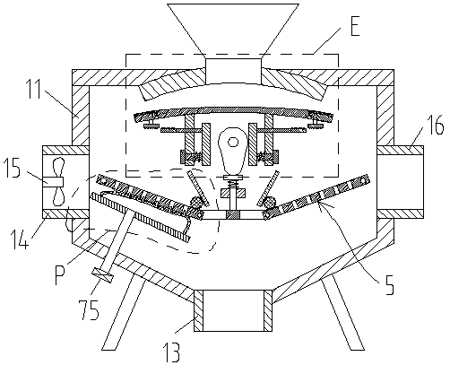
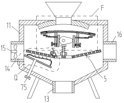
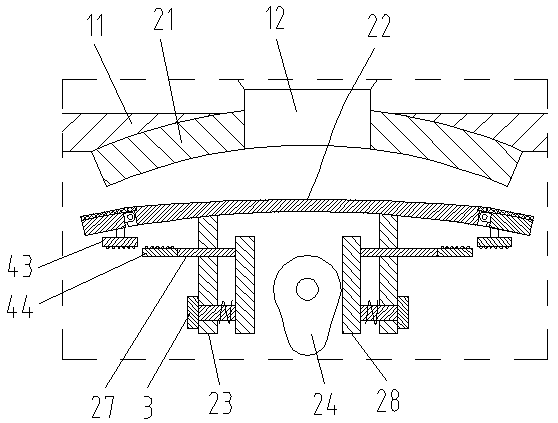
[0029] Such as Figure 1-7 As shown, a grain dedusting device provided by the present invention includes a box body 11, the top of the box body 11 is fixedly connected to the feed pipe 12, the bottom of the box body 11 is fixedly connected to the discharge pipe 13, and one side of the box body 11 is fixedly connected to the air inlet pipe. 14. The air inlet pipe 14 is fixedly connected to the fan 15, the other side of the box body 11 is fixedly connected to the air outlet pipe 16, the top inside the box body 11 is fixedly connected to the first arc-shaped plate 21, and the inside of the box body 11 is slidably connected to the second arc-shaped plate 22. The opposite sides of the second arc-shaped plate 22 are respectively fixedly connected with arc-shaped sliders 25. The inner wall of the box body 11 is provided with an arc-shaped chute 26, and the arc-shaped slider 25 is correspondingly slidably connected in the arc-shaped chute 26. A blanking channel is formed between the f...
Embodiment 2
[0032] Such as Figure 1-6 As shown, on the basis of Embodiment 1, the two ends of the second arc-shaped plate 22 are hingedly connected to the swing plate 41 respectively, the bottom of the swing plate 41 is fixedly connected to the strut 42, and the bottom of the strut 42 is fixedly connected to the first supporting plate 43, close to the second The ends of the guide rods 27 of the two arc-shaped plates 22 are fixedly connected to the second supporting plate 44, and the opposite side of the second supporting plate 44 to the first supporting plate 43 is arranged in a wave shape, and the ends of the second arc-shaped plate 22 are provided with rotating Groove 45, the swing plate 41 is rotatably connected in the swing groove 45, the upper side of the swing groove 45 is provided with a step groove 46, the first rubber film 47 is fixedly connected in the step groove 46, and the first rubber film 47 is fixedly connected to the swing plate 41 On the side, the first rubber film 47 c...
Embodiment 3
[0034] Such as figure 1 , figure 2 , Figure 4 , Figure 7-8 As shown, on the basis of Embodiment 2, two baffle assemblies 5 are connected symmetrically and rotationally in the box body 11. The baffle assembly 5 includes a first U-shaped frame 51 and a second U-shaped frame 52. The first U-shaped frame 51 Form a square frame with the second U-shaped frame 52, the frame of the first U-shaped frame 51 is fixedly connected with the first baffle plate 53, the frame of the second U-shaped frame 52 is fixedly connected with the second baffle plate 54, the first baffle plate 53 A group of through holes 57 are provided on the second baffle plate 54, part of the grains fall directly through the through holes 57, and part of the grains slide down along the upper surfaces of the first baffle plate 53 and the second baffle plate 54, so that the grains are fully dispersed. , to facilitate dust separation, the first baffle plate 53 and the second baffle plate 54 are fixedly connected to...
PUM
 Abstract
Description
Claims
Application Information
 - R&D
- Intellectual Property
- Life Sciences
- Materials
- Tech Scout
- Unparalleled Data Quality
- Higher Quality Content
- 60% Fewer Hallucinations
Browse by: Latest US Patents, China's latest patents, Technical Efficacy Thesaurus, Application Domain, Technology Topic, Popular Technical Reports.
© 2025 PatSnap. All rights reserved.Legal|Privacy policy|Modern Slavery Act Transparency Statement|Sitemap|About US| Contact US: help@patsnap.com


