
Workbench for automobile part punching

A technology for auto parts and workbenches, applied in the field of auto parts, can solve problems such as hole diameter deviation, scrap parts, drill bit deviation, etc., and achieve the effect of preventing deviation

Inactive Publication Date: 2020-04-03
张浩洁
View PDF9 Cites 1 Cited by
  • Summary
  • Abstract
  • Description
  • Claims
  • Application Information

AI Technical Summary

Problems solved by technology

The existing punching workbench often uses a sliding block to slide the parts when fixing the parts, and then fixes them with bolts. If this method is used for positioning, the bolts may be loosened due to vibration during punching, thus Causes the drill bit to shift when drilling, which causes the hole diameter to shift, causing the part to be scrapped

Method used


Image

  • Workbench for automobile part punching
  • Workbench for automobile part punching
  • Workbench for automobile part punching

Examples


Embodiment 1

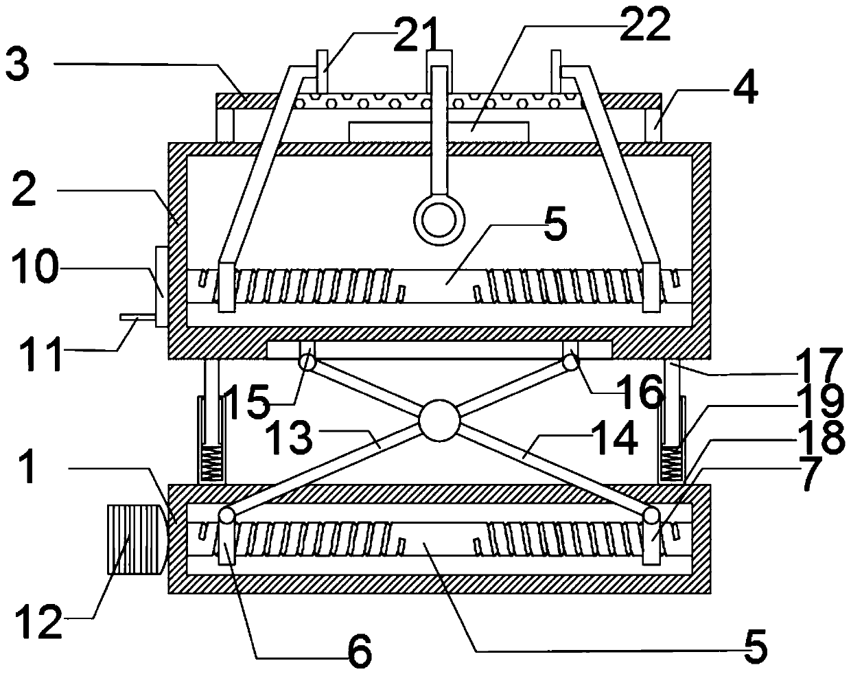
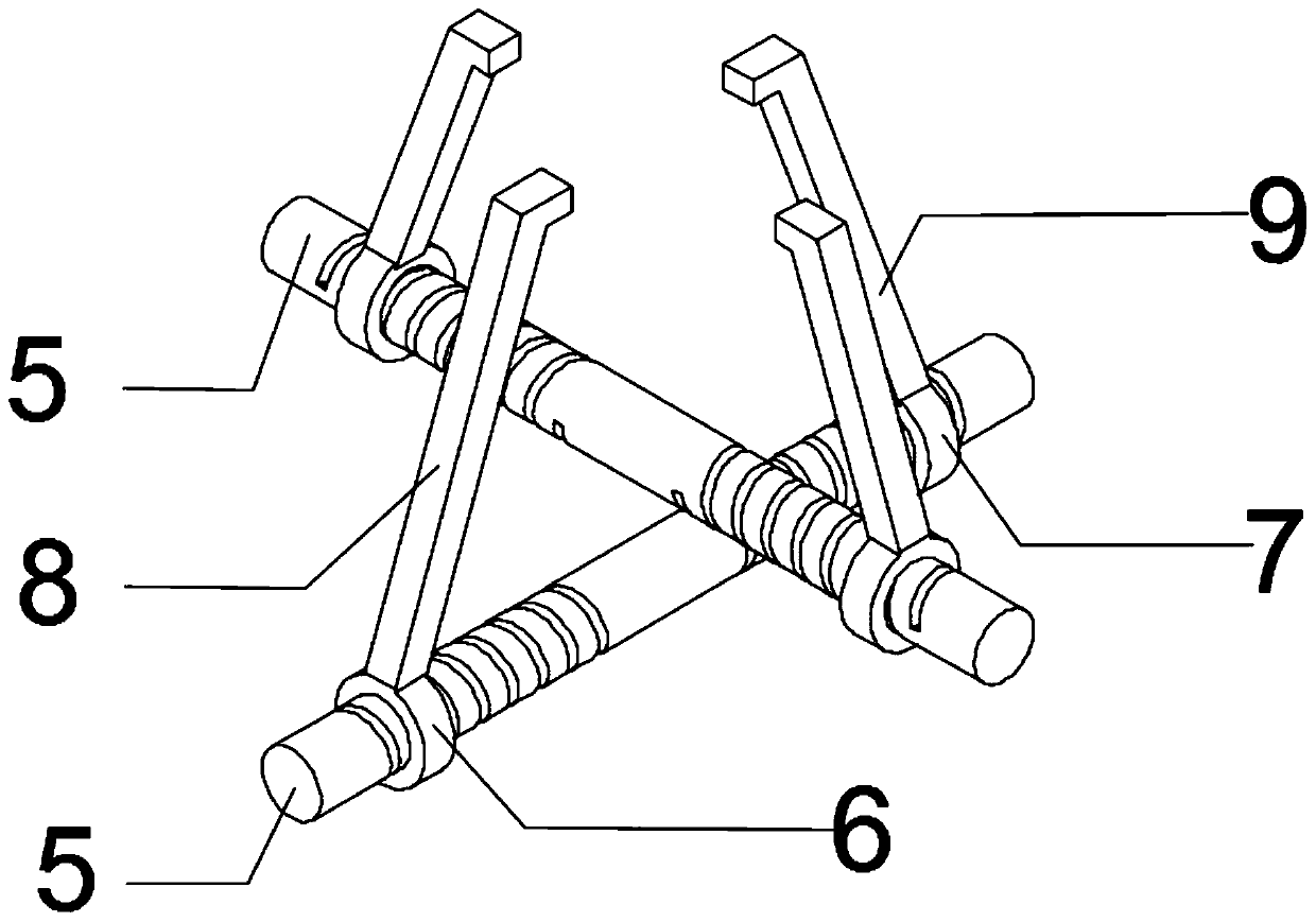
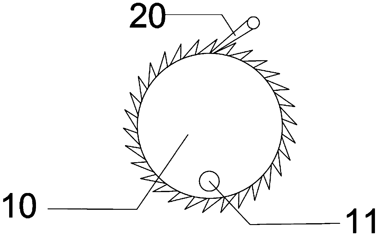
[0019] see Figure 1-3 , this embodiment provides a workbench for punching automobile parts, including a base 1, a workbench 2, a punching platform 3 and a clamping mechanism; the base 1 is provided with a workbench 2; A punching table 3 for placing automobile parts is provided; a punching device is arranged above the punching table 3; a clamping mechanism for clamping automobile parts is also provided on the punching table 3; The mechanism includes a left and right clamping mechanism and a front and rear clamping mechanism; the left and right clamping mechanism and the front and rear clamping mechanism have the same structure, and the two are vertically arranged, respectively located on the left and right sides and the front and rear sides of the auto parts; the left and right clamping mechanisms It includes a clamping rod 5, a left sleeve 6, a right sleeve 7, a left sliding rod 8, a right sliding rod 9, a rotating wheel 10 and a rotating handle 11; On the rotating wheel 10;...

Embodiment 2

[0027] This embodiment is further improved on the basis of Embodiment 1. The improvements are: in order to keep the worktable 2 more stable during the lifting process, a limit mechanism is also set between the worktable 2 and the base 1; The positioning mechanism includes an inner sliding rod 17, an outer fixing sleeve 18 and a spring 19; the bottom of the table 2 is fixed with the upper end of the inner sliding rod 17; the lower end of the inner sliding rod 17 is slidably arranged on the outer fixing sleeve through the spring 19 18; the outer fixing sleeve 18 is also provided with a limit block to prevent the inner sliding rod 17 from being detached; the bottom of the outer fixing sleeve 18 is fixed on the base 1, so that when the worktable 2 is raised and lowered , under the action of the inner sliding rod 17 , the outer fixing sleeve 18 and the spring 19 , the lifting and lowering is more stable.

[0028] In order to further maintain the stability of the worktable 2 during ...


PUM


Abstract

The invention discloses a workbench for automobile part punching. The workbench for automobile part punching comprises a base, a workbench, a punching table and a clamping mechanism. The workbench isarranged on the base; the punching table used for containing an automobile part is arranged on the workbench; a punching device is arranged on the punching table; and the punching table is further provided with the clamping mechanism used for clamping the automobile part. The clamping mechanism comprises a left-right clamping mechanism and a front-back clamping mechanism, wherein the left-right clamping mechanism and the front-back clamping mechanism are the same in structure, are perpendicularly arranged and are located at the left-right sides and the front-back sides of the automobile part correspondingly. According to the workbench for automobile part punching, by arranging the clamping mechanism and a positioning mechanism, the part can be thoroughly fixed, so that the situation that the part deviates in the punching process, and consequently the part is scrapped can be effectively prevented; and by arranging the lifting mechanism, the height of the punching table can be adjusted,and therefore, parts with different heights can be punched smoothly.

Description

technical field [0001] The invention relates to the field of automobile parts, in particular to a workbench for punching holes of automobile parts. Background technique [0002] During the processing of automobile parts, it is often necessary to punch these parts so that multiple parts can cooperate with each other. Now, the punching device is used for punching. These parts are first fixed on the punching table, and then the punching device is used for punching. In the existing punching table, when fixing the parts, the sliding block is often used to slide, and then the bolts are used for fixing. Using this method for positioning, due to vibration during punching, the bolts may be loosened, thereby As a result, the drill bit is offset during drilling, resulting in an offset in the hole diameter and scrapped parts. SUMMARY OF THE INVENTION [0003] The purpose of the present invention is to provide a workbench for punching automobile parts, so as to solve the problems rai...

Claims


Application Information

Patent Timeline
Patent Type & Authority Applications(China)
IPC IPC(8): B23B41/00B23Q1/25B23Q3/06
CPCB23B41/00B23Q1/25B23Q3/06
Inventor 张浩洁
Owner 张浩洁
Learn More