Automatic cloth rolling device used in spinning field

A cloth and automatic technology, which is applied in the field of automatic cloth rolling device in the textile field, can solve the problems that the cloth cannot be rolled neatly, it is not humanized enough, and it cannot be rolled automatically.

Active Publication Date: 2020-04-03
新昌县维利机械有限公司
View PDF15 Cites 2 Cited by
  • Summary
  • Abstract
  • Description
  • Claims
  • Application Information

AI Technical Summary

Problems solved by technology

[0005] In order to solve the above technical problems, the present invention provides an automatic cloth rolling device used in the textile field to solve the problem that the existing textile cloth rolling device usually rolls cloths at different positions and heights When fabrics of different heights fall down, they cannot be guided to be rolled automatically, and the existing textile fabric rolling devices usually require manpower to use fabrics and collecting rollers to connect and wind when collecting fabrics and rolling them. , is not humane enough, and wastes manpower, and when rolling the cloth, the cloth cannot be guided, and the cloth cannot be rolled neatly

Method used


Image

  • Automatic cloth rolling device used in spinning field
  • Automatic cloth rolling device used in spinning field
  • Automatic cloth rolling device used in spinning field

Examples


Embodiment

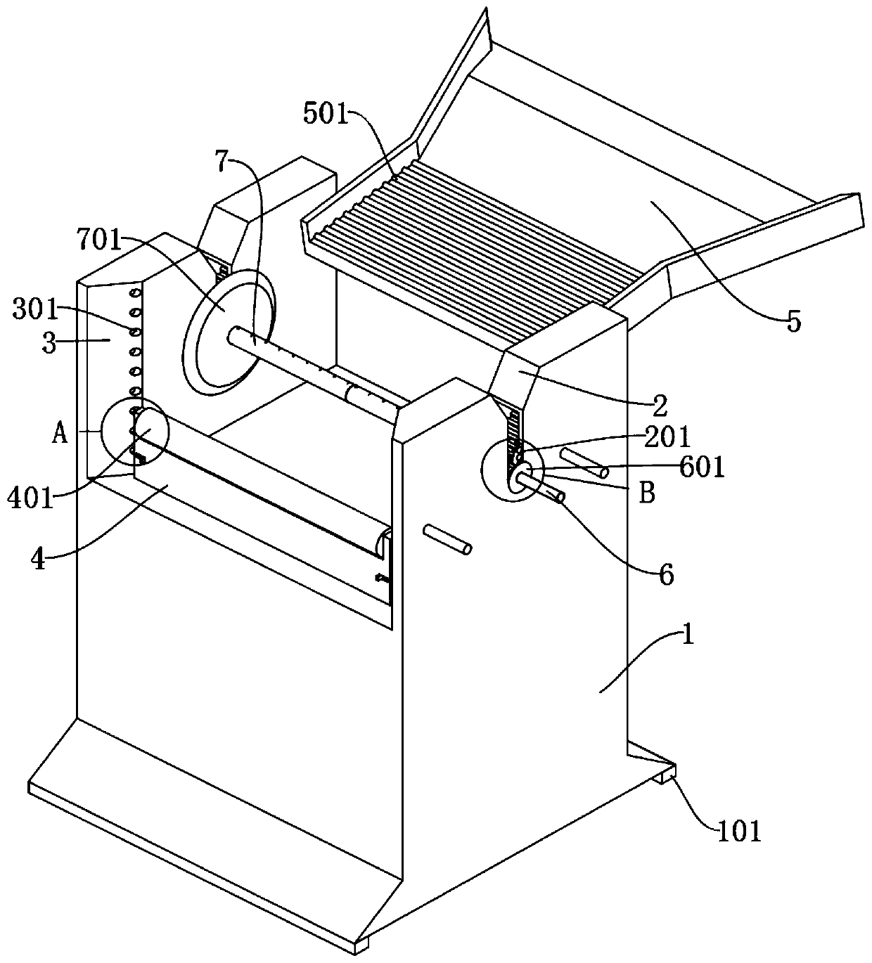
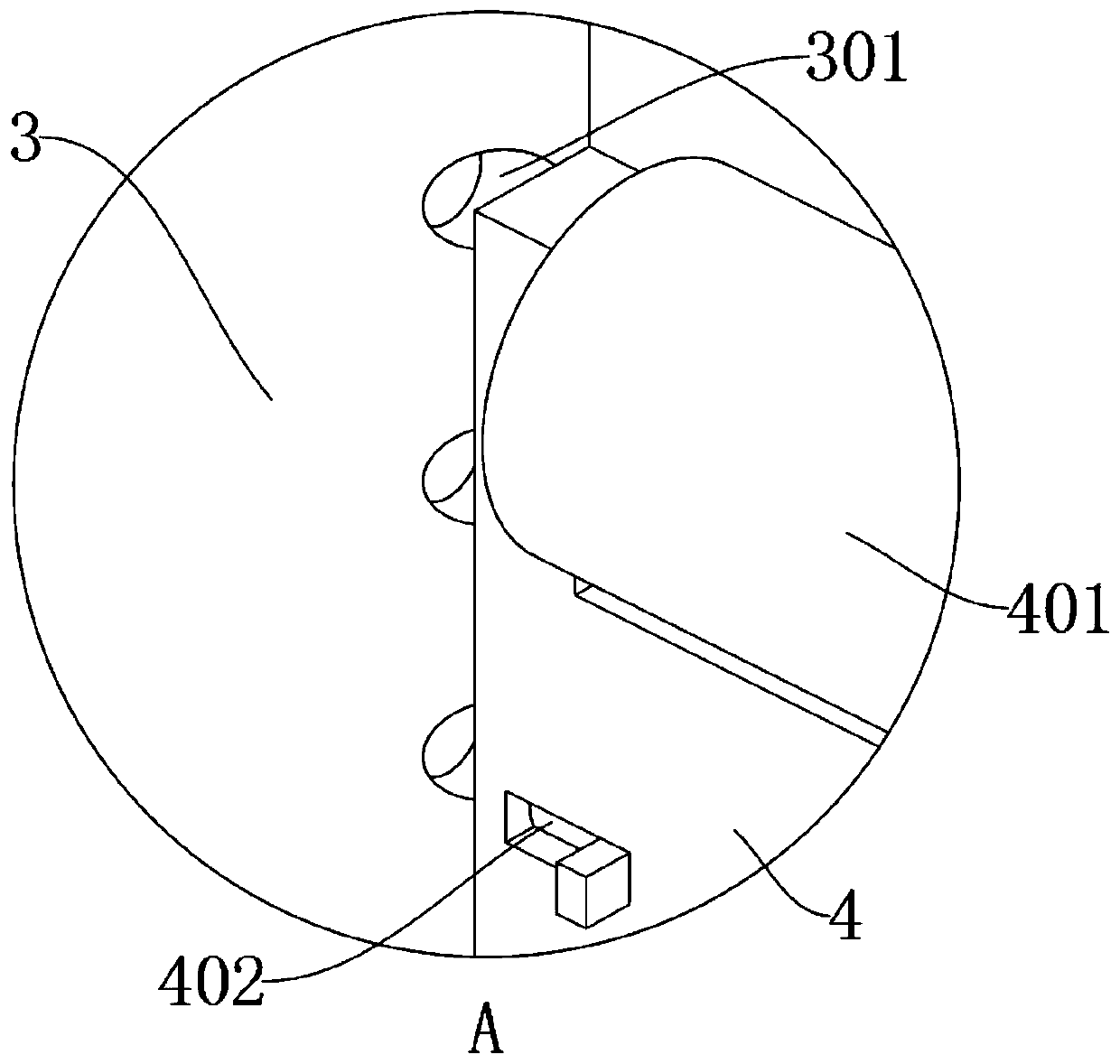
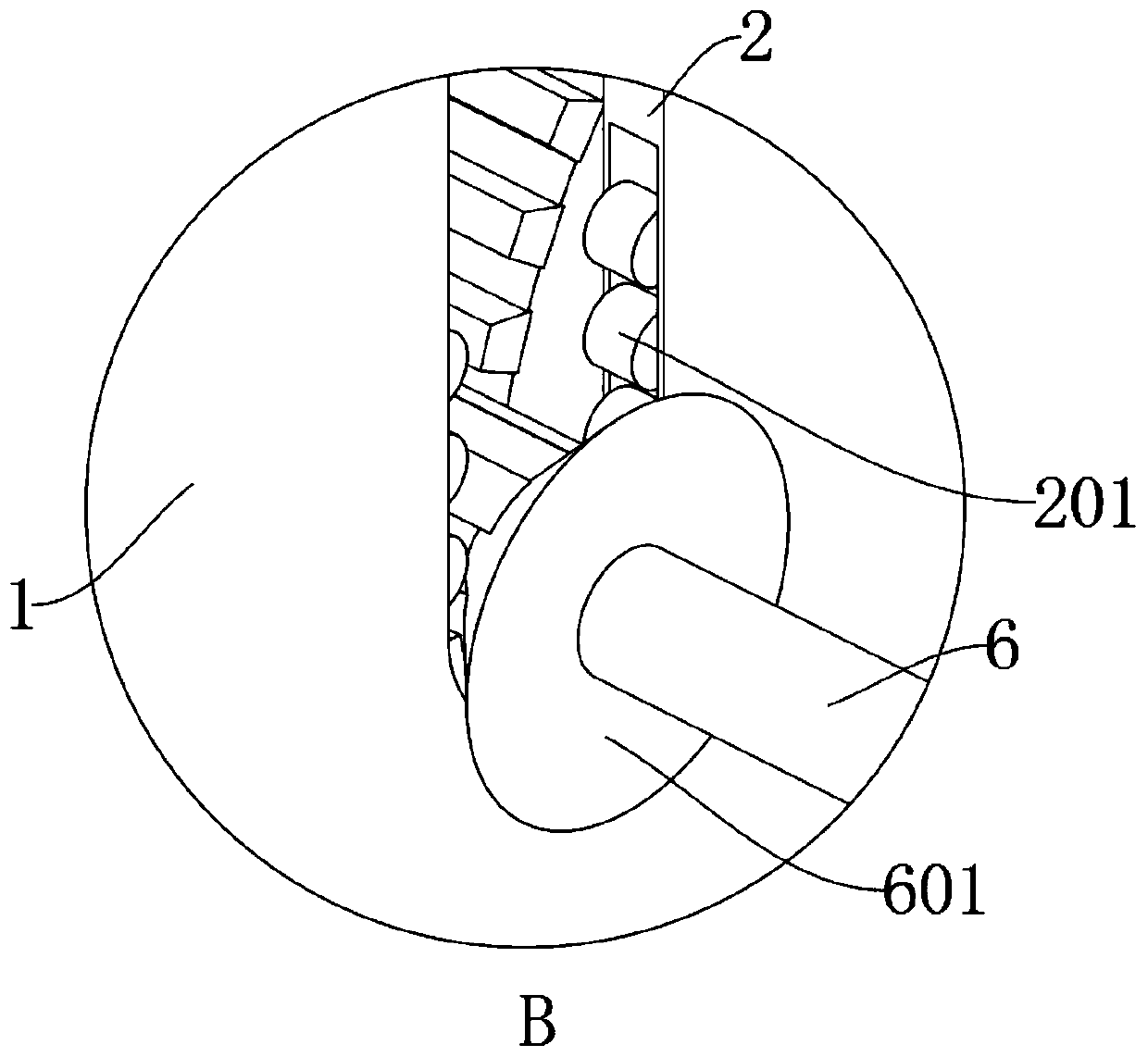
[0032] as attached figure 1 To attach Figure 8 Shown:

[0033]The present invention provides an automatic cloth rolling device used in the textile field, comprising: a main body 1, a top groove 2, a side groove 3, a moving part 4, a guide 5, an outer rod 6 and a connecting rod 7; the top end of the main body 1 There is a rectangular installation groove, and the bottom of the main body 1 is provided with a rectangular inner groove, and the bottom piece 101 is made of rubber, so that it can better contact the ground, so that when the main body 1 is in use, it will not The vibration is transmitted to the ground; the bottom of the top groove 2 is an arc-shaped structure, and the top groove 2 is set in the middle of the top of both sides of the main body 1, and the pulley 201 inside the top groove 2 is used to contact the outside of the outer rod 6 When the outer rod 6 is in use, it can contact the inside of the top groove 2 through the pulley 201, so as to prevent the inside of...


PUM


Abstract

The invention provides an automatic cloth rolling device used in the spinning field. The automatic cloth rolling device comprises a body, top grooves, side grooves, a moving part, a guide part, an outer rod and a connecting rod. An installation groove of a rectangular structure is formed in the top end of the body, and an inner groove of a rectangular structure is formed in the bottom of the body.The bottoms of the top grooves are of arc structures, and the top grooves are formed in the middle positions of the top ends of the two sides of the body. The side grooves are formed in the two sidesof the upper end of the upper portion of the body. The moving part is of a rectangular plate-shaped structure. The moving part is used for being installed at the front end of the body so that when the device is used for rolling cloth at different heights, the moving part can be used for driving a guide roller to be located at different heights, and therefore the cloth discharged from production lines at different height can be guided to the outer side of the connecting rod, and the cloth can be automatically collected conveniently; and the moving part is of the rectangular plate-shaped structure, and therefore the moving part can be moved and adjusted conveniently in the body.

Description

technical field [0001] The invention belongs to the technical field of textiles, and more specifically relates to an automatic cloth rolling device used in the textile field. Background technique [0002] In the textile industry, rolling the cloth from small to large on a paper tube or other circular tube is called rolling, which can facilitate the processing of gray cloth in various processes. Due to the different processes, the rolled not exactly. [0003] For example, the application number: CN201810885296.8 relates to a continuous rolling device for textile printing and dyeing cloth, including a left switch support plate and a right switch support plate facing left and right; the left switch support plate is pivotally connected to the level of the left side support plate The right end surface of the part; the right switching support plate is pivotally connected to the left end surface of the horizontal part of the side support plate on the right; The reel is sleeved fr...

Claims


Application Information

Patent Timeline
Patent Type & Authority Applications(China)
IPC IPC(8): B65H23/26B65H18/02B65H18/10B65H19/28
CPCB65H18/028B65H18/10B65H19/28B65H23/26B65H2701/1133B65H2701/174
Inventor 宋旭
Owner 新昌县维利机械有限公司
Why Eureka
Try Eureka