Cantilevered floor slab rebar structure adopting steel bar truss formworks and bar reinforcing method

A steel truss and steel bar technology is applied in the field of concrete pouring formwork, which can solve the problems of long construction period, difficulty in supporting formwork and high cost, and achieve the effects of improving efficiency, reducing the workload of reinforcing steel bar binding, and shortening the construction period.

Pending Publication Date: 2020-04-03
北京建工集团山西建设有限公司
View PDF0 Cites 0 Cited by
  • Summary
  • Abstract
  • Description
  • Claims
  • Application Information

AI Technical Summary

Problems solved by technology

[0003] The present invention provides a cantilevered floor slab reinforcement structure and reinforcement method using reinforced truss formwork, which solves the difficulties, long constr

Method used


Image

  • Cantilevered floor slab rebar structure adopting steel bar truss formworks and bar reinforcing method
  • Cantilevered floor slab rebar structure adopting steel bar truss formworks and bar reinforcing method
  • Cantilevered floor slab rebar structure adopting steel bar truss formworks and bar reinforcing method

Examples


Embodiment Construction

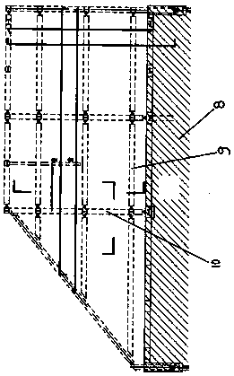
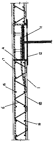
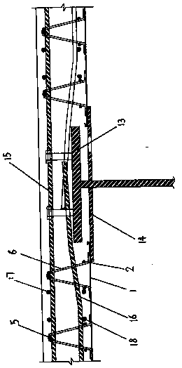
[0012] The present invention is described in detail below in conjunction with accompanying drawing:

[0013] A reinforced structure of cast-in-place cantilevered floor slabs using steel truss formwork, including a main building structure 8, and a steel beam suspension composed of steel beams 9 parallel to the direction of the main building and steel beams 10 perpendicular to the direction of the main building cantilevered on the outside of the main building structure 8 On the pick frame, the steel beam 9 parallel to the main building direction is provided with a steel beam panel 11 parallel to the main building direction, and the steel girder steel supporting plate 12 parallel to the main building direction is arranged on the I-steel vertical plate below the steel beam panel 11 parallel to the main building direction. The steel girder 10 perpendicular to the direction of the main building is provided with a steel beam panel 13 perpendicular to the direction of the main building...


PUM


Abstract

The invention discloses a cantilevered floor slab rebar structure adopting steel bar truss formworks and a bar reinforcing method. The problem that support formworks of a cast-in-place cantilevered reinforced concrete floor slab of an existing high-altitude cantilever floor have support difficulties and are long in construction period and high in construction price is solved. A main building structure (8) is included, a steel beam cantilever frame composed of steel beams (9) parallel to the main building direction and steel beams (10) perpendicular to the main building direction is arranged onthe outer side of the main building structure (8) in an overhang manner, steel beam panels (11) parallel to the main building direction are arranged on the steel beams (9) parallel to the main building direction, and steel beam panels (13) perpendicular to the main building direction are arranged on the steel beams (10) perpendicular to the main building direction, the steel bar truss formworks are fixedly welded to the steel beam cantilever frame and are composed of rectangular bottom mold steel plates (1) and steel bar framed bents fixedly arranged in the left-right direction at intervals,and the steel bar framed bents are fixedly arranged on the rectangular bottom mold steel plates in the left-right direction. The on-site reinforcement lashing workload can be reduced by 60% to 70%.

Description

technical field [0001] The invention relates to a concrete pouring formwork, in particular to a reinforcement structure and reinforcement method for a concrete floor slab of a cast-in-place high-position cantilevered building. Background technique [0002] In the existing tower structure, a high-altitude large-span cantilevered building structure is often designed. The high-altitude large-span cantilevered building is generally supported by a steel structure frame, and cast-in-place reinforced concrete beams, slabs, and external frame beams; for cast-in-place cantilevered reinforced concrete If the floor is constructed with traditional wooden formwork, it cannot meet the support strength of the bottom formwork of the cast-in-place reinforced concrete floor at the bottom of the high cantilevered building. The existing technology is to use profiled steel plates as the bottom formwork, but when the bottom of the floor is encountered, the formwork cannot be set. When supporting ...

Claims


Application Information

Patent Timeline
IPC IPC(8): E04B1/00E04G11/36E04G11/48E04B5/32
CPCE04B1/00E04B5/32E04G11/36E04G11/48
Inventor 景耀辉王振先桑明辉张海波陈宏孙鹏高梅苏亚萍任建刘天文李永峰韩梦云
Owner 北京建工集团山西建设有限公司
Why Eureka
Try Eureka