Building curtain wall mounting and fixing device

A technology of fixing device and curtain wall, applied in the direction of building, building components, building structure, etc., can solve the problem that the angle of the curtain wall cannot be easily adjusted, and achieve the effect of increasing stability and avoiding the rotation of the main body

Inactive Publication Date: 2020-04-03
中建河图建设有限公司
View PDF1 Cites 3 Cited by
  • Summary
  • Abstract
  • Description
  • Claims
  • Application Information

AI Technical Summary

Problems solved by technology

[0004] Based on the technical problem that the angle of the curtain wall cannot be easily adjusted when the curtain wall is installed, this invention proposes a building curtain wall installation and fixing device

Method used


Image

  • Building curtain wall mounting and fixing device
  • Building curtain wall mounting and fixing device
  • Building curtain wall mounting and fixing device

Examples


Embodiment 1

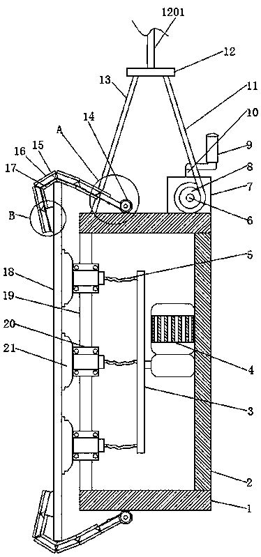
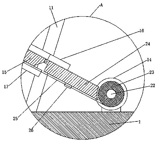
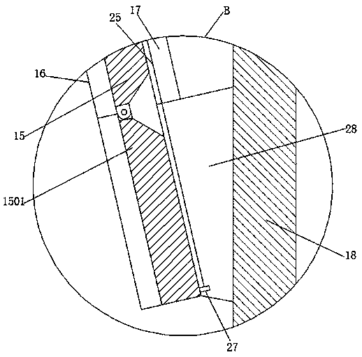
[0031] refer to Figure 1-6 , a building curtain wall installation and fixing device, including a main body 1 and a curtain wall 18, one side of the main body 1 is welded with a connecting plate 2, one side of the connecting plate 2 is fixedly connected with an air pump 4, and the output end of the air pump 4 is fixed by a flange It is connected with a trachea 3, the two sides of the trachea 3 are provided with suction holes, the trachea 3 is provided with a hose 5 at the suction hole, the other side of the main body 1 is welded with two fixed bodies 19, and one side of the fixed body 19 is welded There is a fixed fastener 20, and the middle part of the fixed fastener 20 is provided with a vacuum suction cup 21, and the fixed fastener 20 is fixedly connected with the vacuum suction cup 21 by fixing bolts. 5 bonding, one side of the top of the main body 1 is provided with a fixed rope 13, the top of the fixed rope 13 is provided with a moving plate 12, the top of the moving pla...

Embodiment 2

[0043] refer to Figure 7 , a building curtain wall installation and fixing device. Compared with Embodiment 1, in order to increase the practicability of the device and avoid mutual influence between the vacuum suction cups 21, a valve 33 is provided at the connection between the vacuum suction cups 21 and the hose 5. The valve 33 can ensure that the vacuum suction cups 21 will not interact with each other, so as to prevent the curtain wall 18 from losing suction and falling.

[0044] When in use, start the air pump 4 to pump air, and make the vacuum suction cup 21 suck the curtain wall 18 through the air pipe 3 and the flexible pipe 5. The valve 33 can ensure that the vacuum suction cups 21 will not affect each other, so as to prevent the curtain wall 18 from losing its suction and falling. The curtain wall 18 is moved to a designated position by the lifting rope 1201 and the moving plate 12. At this time, by rotating the rocker 9, the worm 10 drives the worm wheel 30 to rot...


PUM


Abstract

The invention belongs to the technical field of building engineering equipment, particularly relates to a building curtain wall mounting and fixing device. For the problem that the angle of a curtainwall cannot be adjusted easily when the curtain wall is mounted, the scheme is provided; according to the scheme, the building curtain wall mounting and fixing device comprises a main body and a curtain wall, a connecting plate is welded to one side of the main body, one side of the connecting plate is fixedly connected with an air pump through bolts, the output end of the air pump is fixedly connected with an air pipe through a flange, and air suction holes are formed in the two sides of the air pipe; and hoses are arranged at the air suction hole positions of the air pipe, two fixing bodiesare welded to the other side of the main body, and fixing fasteners are welded to one sides of the fixing bodies. According to the building curtain wall mounting and fixing device, a worm drives a worm gear to rotate, the worm gear drives a rotating shaft to rotate, the rotating shaft drives a first pulley to rotate, the first pulley makes a rigid rope be shortened or elongated, due to the fact that a fixing rope and the rigid rope are located on the two sides of the top end of the main body, the rigid rope is shortened to make the main body deflect counterclockwise, the rigid rope is elongated to make the main body deflect clockwise, and the mounting angle of the curtain wall is changed conveniently.

Description

technical field [0001] The invention relates to the technical field of building engineering equipment, in particular to a building curtain wall installation and fixing device. Background technique [0002] Building curtain wall is the outer protective structure or decorative structure of the building. In the modern city construction, the curtain wall industry is booming, but the installation of the curtain wall is more troublesome. Generally, it needs to be fixed by the device and transported to the designated location. The curtain wall cannot be easily adjusted during installation. The angle of the curtain wall will cause inconvenience to the installation of the curtain wall. [0003] After retrieval, the Chinese patent application number is CN201620825069.2, which discloses a curtain wall vacuum suction cup installation system. The vacuum suction cup installation system is composed of a vacuum suction cup system and a robotic arm system; The existing six-axis manipulator ...

Claims


Application Information

Patent Timeline
Patent Type & Authority Applications(China)
IPC IPC(8): E04B2/88
CPCE04B2/88
Inventor 王凡钱光华林少龙徐盖陈子杰陈登意张敏
Owner 中建河图建设有限公司
Why Eureka
Try Eureka