An adjustable plug-in pendant structure equipped with springs

An adjustable, plug-in technology, applied in building construction, covering/lining, construction, etc., can solve the problems of installation and disassembly difficult to locate, hidden safety hazards, difficult to repair, etc., to achieve the effect of convenient adjustment

Active Publication Date: 2021-04-06
CHONGQING IND POLYTECHNIC COLLEGE
View PDF5 Cites 0 Cited by
  • Summary
  • Abstract
  • Description
  • Claims
  • Application Information

AI Technical Summary

Problems solved by technology

Since the bottom of the stone veneer needs to be supported and stuck by the pre-fixed T-shaped pendant, this method can only be installed one by one from bottom to top. After the installation is completed, if the middle panel is damaged, it is very difficult to repair
Even if the repaired stone veneer is difficult to be hung by the pre-fixed T-shaped pendant, it can only be fixed by glue, which poses a serious safety hazard
The applicant has designed plug-in pendants before, but it was found in the application that these designs all have a defect. When the decorative board is dug into the hanging groove, in order to allow the plug-in block and the magnetic block below the plug-in block to have a movable space, the decorative board is facing inward. On one side of the wall, the hanging groove needs to dig a space of more than 6 mm upwards, leaving a place for the magnet to move under the insertion block, which weakens the strength of the hanging part of the decorative panel, and makes it difficult to locate and fast enough during installation and disassembly , and there is no recessed or protruding adjustment mechanism, it is difficult to guarantee the flatness of the surface for changing the veneer with different thickness, especially the disassembly requires special tools, which limits the promotion of this kind of pendant

Method used


Image

  • An adjustable plug-in pendant structure equipped with springs
  • An adjustable plug-in pendant structure equipped with springs
  • An adjustable plug-in pendant structure equipped with springs

Examples


Embodiment Construction

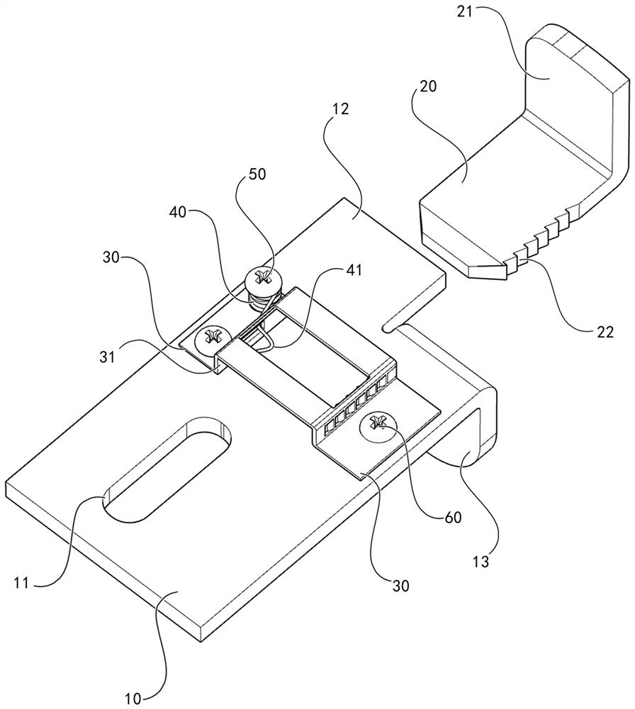
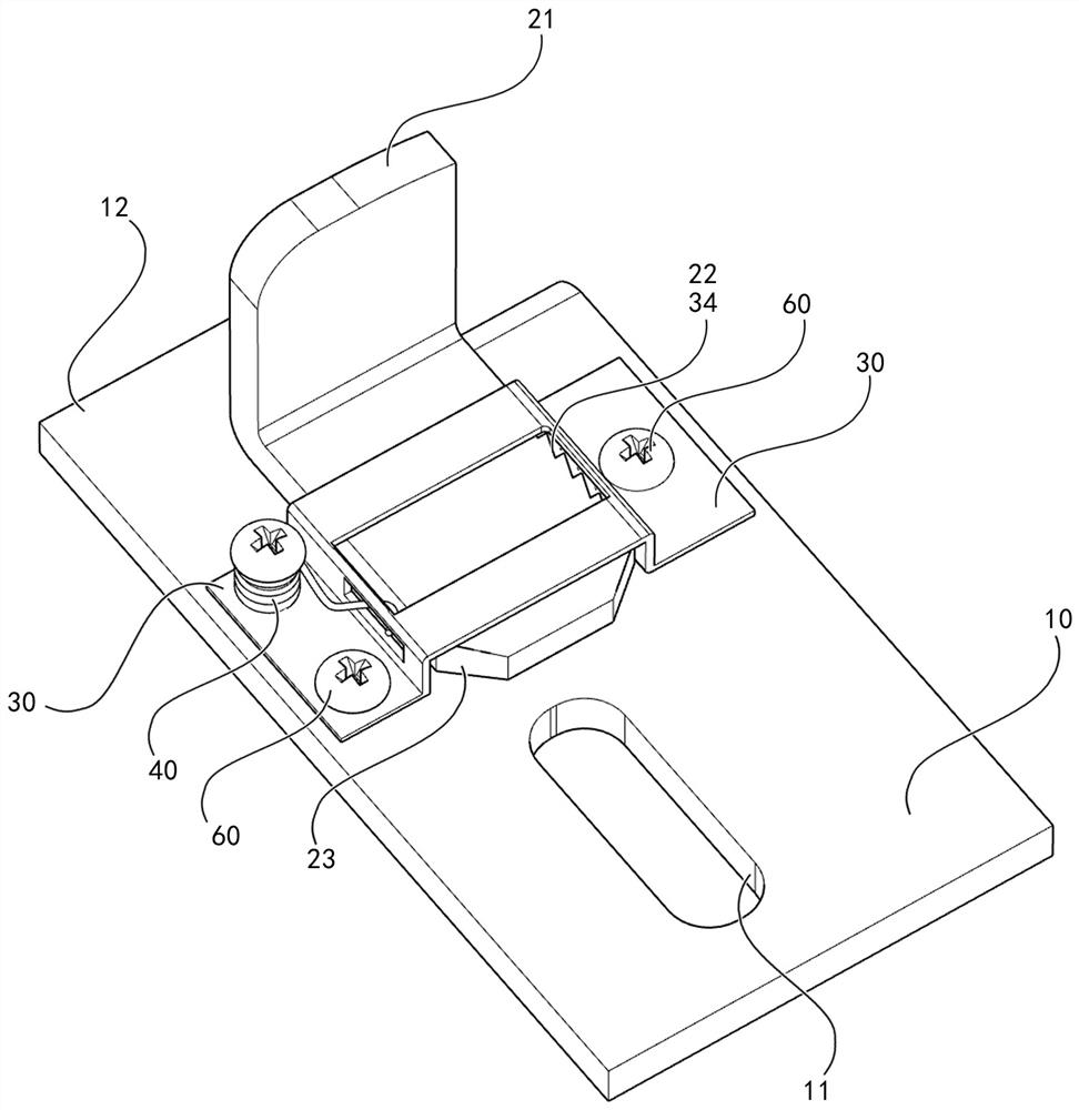
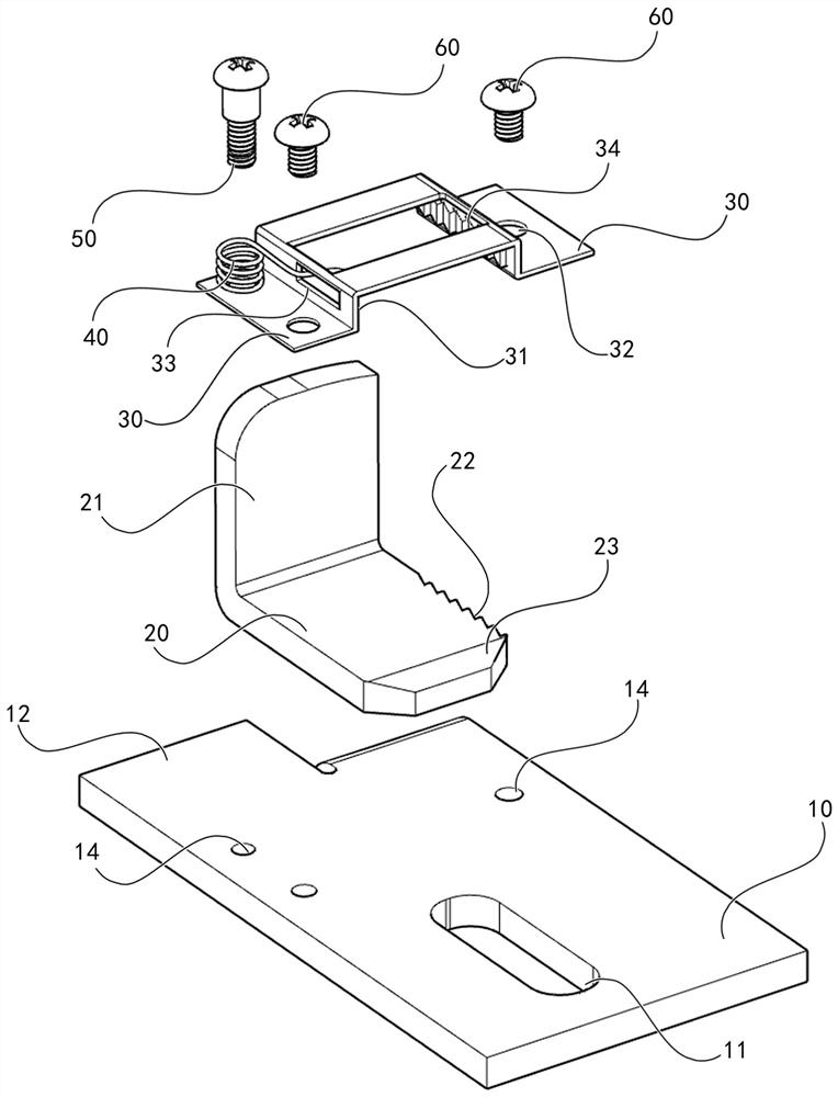
[0017]Next, the present invention will be further explained in conjunction with the accompanying drawings and examples:Figure 1 to 4As shown, an adjustable plug-in structure having a spring, including a pallet 10, a block 20, a positioning cover 30, a spring ring 40, a spring limit plug 50, a screw 60, which is characterized in that the support is The rear end of the plate 10 is provided with a positioning bolt hole 11, and the front end is provided with a strut 12 and a lower hook head 13, and the intermediate is provided with a threaded hole 14; the front end of the insert block 20 is provided with a hook head 21 rear end setting with a slope 23, right The side is provided with a positioning slope 22; a through hole 32 is provided on both sides of the positioning cover 30, and the intermediate is provided with a block passage 31, and the spring groove 33 is provided on one side of the block passage 31 is provided. The other side is provided with reverse Tottess 34; the screw 60 is...


PUM


Abstract

An adjustable plug-in pendant structure equipped with a spring, including a supporting plate, an inserting block, a positioning cover, a spring coil, a spring limit bolt, and a screw; it is characterized in that the rear end of the supporting plate is provided with positioning bolt holes, The front end is provided with a bracket and the lower hook head, and the middle is provided with a threaded hole; the front end of the insertion block is provided with an upper hook head, and the rear end is provided with a slope, and the right side is provided with positioning helical teeth; the two sides of the positioning cover are provided with through holes. There is an insertion block channel in the middle, a spring slot is provided on one side of the insertion block channel, and a reverse helical tooth is provided on the other side; the screw passes through the through hole to fix the positioning cover on the supporting plate; the spring The ring is fixed on the side of the positioning cover plate provided with the spring groove by the spring limit bolt; the straight end of the spring ring is fixed outside the channel of the insertion block, and the elbow is placed in the spring groove. The present invention can realize multi-station rapid installation and disassembly of stone panels with different thicknesses on the basis of pre-fixed pendants, and does not require special tools.

Description

Technical field[0001]The present invention relates to a building exterior wall-forming panel fixing technique, and more particularly to an adjustable plug-in pendant structure mounted with a spring.Background technique[0002]At present, most of the mounting stone panels in the building uses a steel frame dry-mounted method, which is used to embed the groove of the upper and lower adjacent stone panels with a T-shaped pendant and fixed to the adhesive filling. Since the lower side of the stone panel needs to be held in advance, the T-shaped pendant is kept, the method generally only installs from the lower to the bottom, after the installation is complete, if the intermediate panel is damaged, it is very difficult to repair. Even if the repaired stone panel is also hung by it is difficult to be fixed by a prior fixed T-shaped pendant, it can only be adopted, there is a serious safety hazard. The applicant has been designed with an inserted pendant, but it is found that these designs h...

Claims


Application Information

Patent Timeline
Patent Type & Authority Patents(China)
IPC IPC(8): E04F13/28
CPCE04F13/0821
Inventor 苏涛吴优美朋宇白雪欧阳婧芸高彬洁
Owner CHONGQING IND POLYTECHNIC COLLEGE
Why Eureka
Try Eureka