
Equipment for detecting computer case finished product by utilizing punching pressure

A computer case and testing equipment technology, applied in the direction of measuring devices, instruments, scientific instruments, etc., can solve the problems of reducing work efficiency, wasting materials, and position deviation

Active Publication Date: 2020-04-03
广州嘉泰电脑设备有限公司
View PDF5 Cites 6 Cited by
  • Summary
  • Abstract
  • Description
  • Claims
  • Application Information

AI Technical Summary

Problems solved by technology

[0003] During the manufacturing process of the computer case, it is necessary to use a punching drill to punch holes in the board. The traditional punching drill needs to be hand-held to the chassis board during the drilling process, and lacks a positioning and clamping mechanism, resulting in the same assembly line. The position of the hole is deviated, which affects later sales, and the clamping force of the existing clamping mechanism is fixed, causing the chassis board to be deformed by a large clamping force for a long time; in addition, after the chassis board is manufactured, it needs to Conduct strength testing, while traditional testing is placed at the last step of the production process and has nothing to do with production steps such as drilling, resulting in drilling and painting processes for unqualified products, which wastes materials and reduces work efficiency. A device for testing finished computer cases using punching pressure came into being

Method used


Image

  • Equipment for detecting computer case finished product by utilizing punching pressure
  • Equipment for detecting computer case finished product by utilizing punching pressure
  • Equipment for detecting computer case finished product by utilizing punching pressure

Examples


Embodiment Construction

[0024] The following will clearly and completely describe the technical solutions in the embodiments of the present invention with reference to the accompanying drawings in the embodiments of the present invention. Obviously, the described embodiments are only some, not all, embodiments of the present invention. Based on the embodiments of the present invention, all other embodiments obtained by persons of ordinary skill in the art without making creative efforts belong to the protection scope of the present invention.

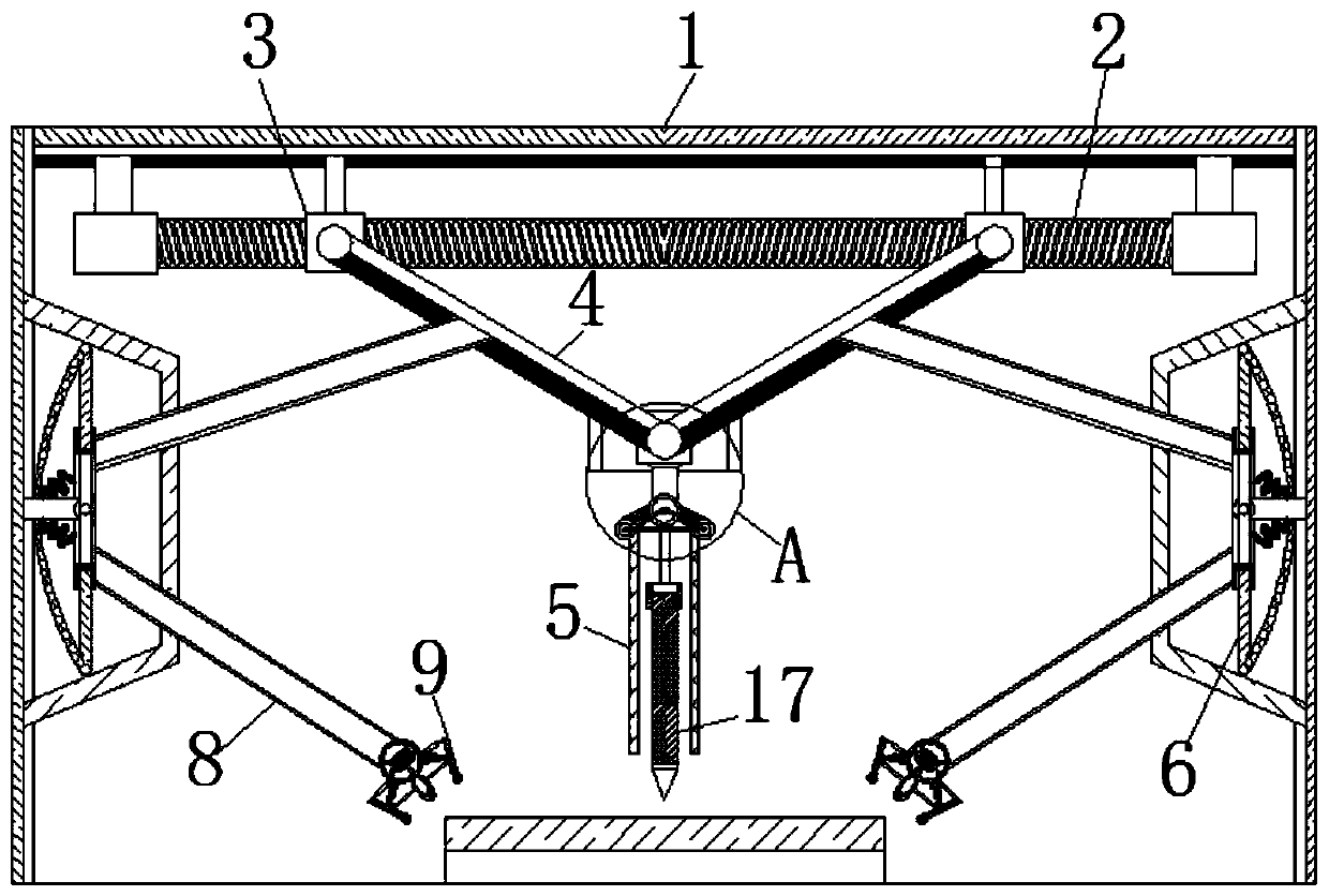
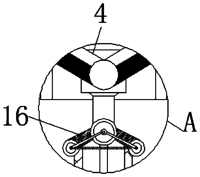
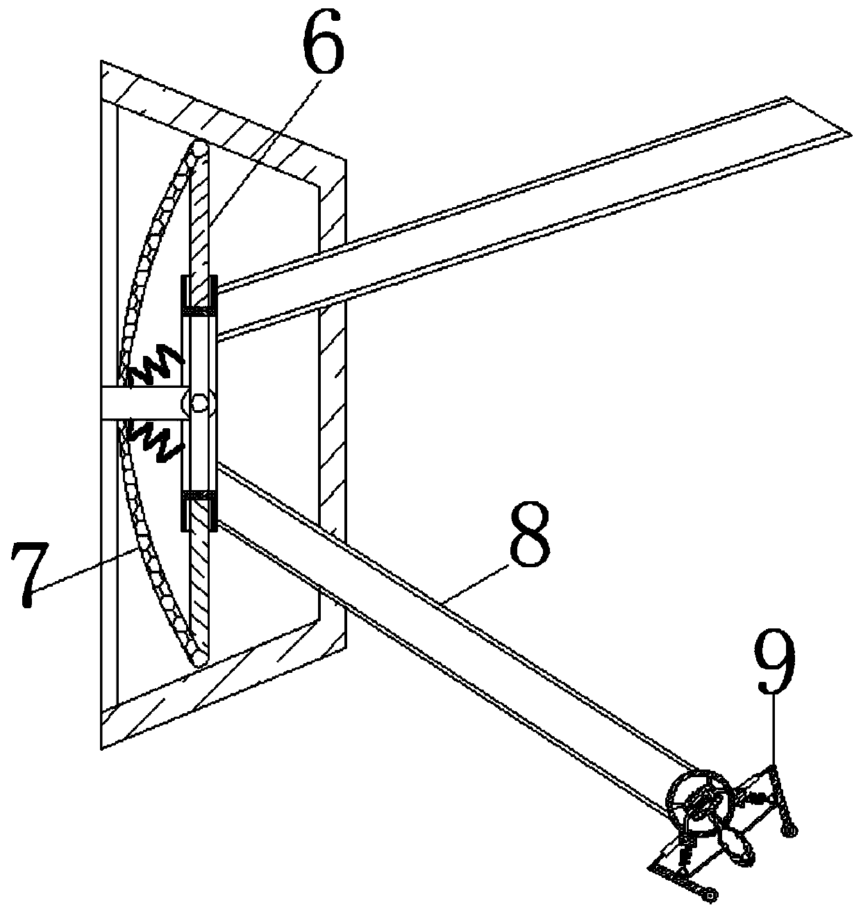
[0025] see Figure 1-7 , a kind of testing equipment for the finished product of the computer case by punching pressure, comprising a casing 1, the inside of the casing 1 is movably connected with a rotating shaft 2, the surface of the rotating shaft 2 is movably connected with an engaging block 3, and the surface of the engaging block 3 is movably connected with Sliding bar 4, one end of sliding bar 4 away from engaging block 3 is movably connected with punch...


PUM


Abstract

The invention relates to the technical field of computer case punching and detection and further discloses equipment for detecting the computer case finished product by utilizing the punching pressure. The equipment comprises a shell, a rotating shaft is movably connected into the shell, a meshing block is movably connected to the surface of the rotating shaft, a sliding rod is movably connected to the surface of the meshing block, a punching part is movably connected to the end, away from the meshing block, of the sliding rod, a lever is slidably connected to the surface of the sliding rod, and an air bag is movably connected to the surface of the lever. The rotating shaft rotates to drive the meshing block to move from the surface to the center of the shell. In the process that the meshing block moves towards the center of the shell, the sliding rod is driven to move away from the rotating shaft; the clamping rods are guided by the guide wheels to be clamped on the upper portion andthe side face of the case plate respectively, the clamping rods can pull the ropes to compress the springs, and due to the fact that the movement displacement of the rods of the detection rods is related to the deflection angle of the lever, the effect that the clamping force changes along with the change of the punching force is achieved.

Description

technical field [0001] The invention relates to the technical field of punching and testing computer cases, in particular to a device for testing finished computer cases using punching pressure. Background technique [0002] As a part of computer accessories, the chassis is mainly used to place and fix various computer accessories, and play a supporting and protective role; most of the chassis are made of metal materials. In order to facilitate the placement of electronic components inside the computer, the chassis board often has A certain shape, and holes are opened on the surface, which is convenient for heat dissipation when computer electronic components work. [0003] During the manufacturing process of the computer case, it is necessary to use a punching drill to punch holes in the board. The traditional punching drill needs to be hand-held to the chassis board during the drilling process, and lacks a positioning and clamping mechanism, resulting in the same assembly ...

Claims


Application Information

Patent Timeline
IPC IPC(8): G01N3/04
CPCG01N3/04G01N2203/0019G01N2203/04
Inventor 刘改林作泉
Owner 广州嘉泰电脑设备有限公司
Learn More