Steel bar joint identification using artificial intelligence vision

A technology of artificial intelligence and steel bars, applied in the direction of collaborative operation devices, construction material processing, instruments, etc., can solve problems such as high physical requirements, increased risk of injury, and time-consuming

Pending Publication Date: 2020-04-03
LOGISTICS & SUPPLY CHAIN MULTITECH R&D CENT LTD
View PDF0 Cites 3 Cited by
  • Summary
  • Abstract
  • Description
  • Claims
  • Application Information

AI Technical Summary

Problems solved by technology

Tying rebar along wide pavements is repetitive, time-consuming, and physically demanding work
Also, it is not safe to walk on the steel mesh at the construction site
Having many construction crews working and walking on the steel grid only significantly increases the risk of injury

Method used


Image

  • Steel bar joint identification using artificial intelligence vision
  • Steel bar joint identification using artificial intelligence vision
  • Steel bar joint identification using artificial intelligence vision

Examples


Embodiment Construction

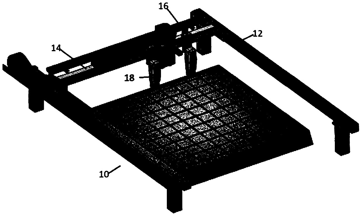
[0035] The inventors, through their own research, trials and experiments, have devised a routine that can use robotic tools to assist in the rebar binding process.

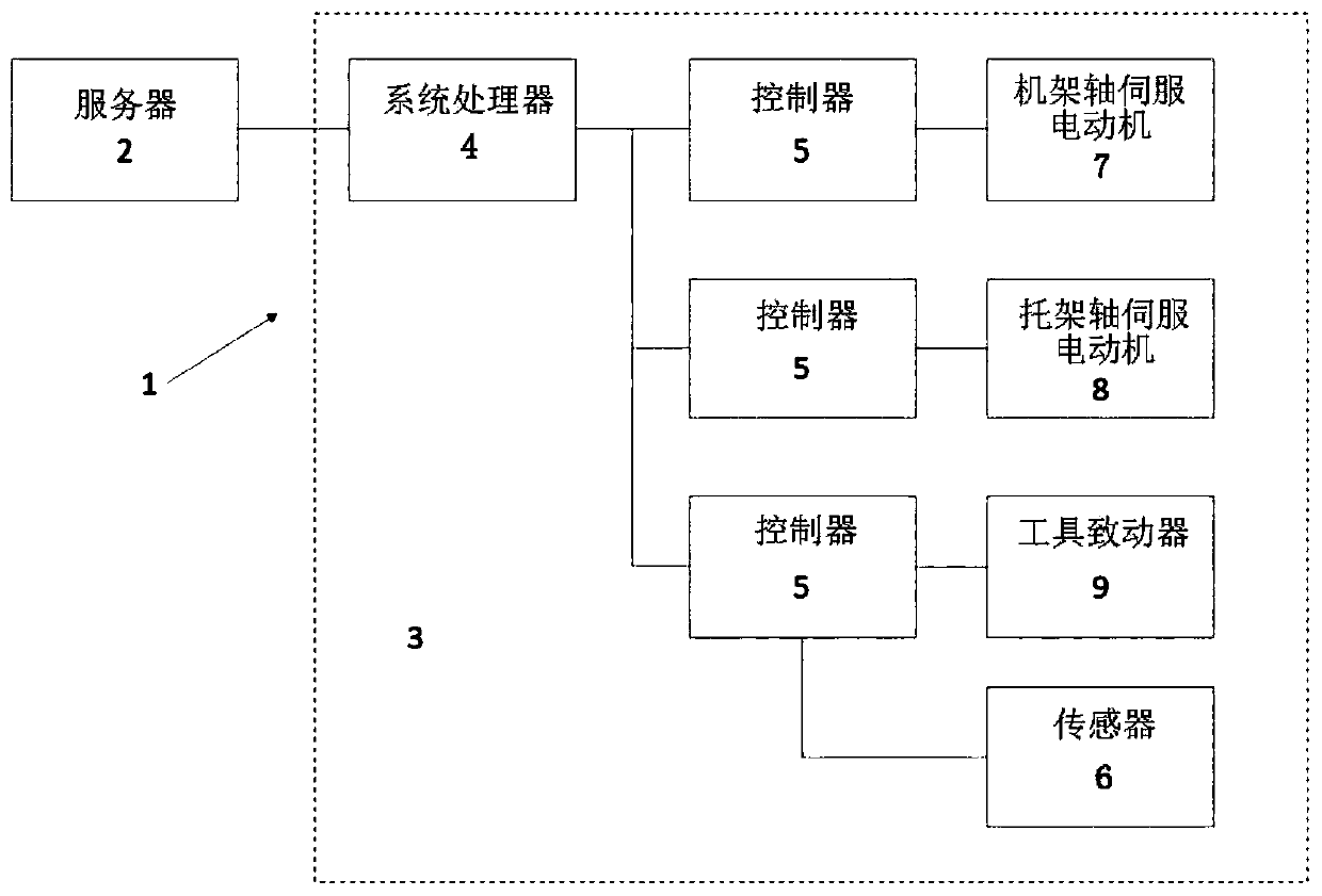
[0036] In one exemplary embodiment, an apparatus may be used to bundle longitudinal and transverse pavement rebar in a rectangular arrangement. The device may consist of a self-propelled frame assembly. The self-propelled frame assembly includes means for lifting each individual bar of the longitudinally aligned bars and for periodically placing the transverse bars in a plurality of binding straps disposed at selected intersections of the longitudinal and transverse bars Tied with raised transverse reinforcement. The self-propelled frame also includes means arranged transversely for supporting a plurality of longitudinal rebars and inserting transverse rebars underneath to receive the strapping; The frame assembly is intermittently driven on the frame to effect binding on every other longitudinal bar. The next ...


PUM


Abstract

An apparatus or system for rebar (bar) contact identification using artificial intelligence vision includes a rebar tying tool connected to a micromanipulator; a macro manipulator which is used for moving the position of the micro manipulator, wherein the macro manipulator is adapted to move the micro manipulator on a first plane, and the micromanipulator is adapted to move the rebar tying tool ona second plane parallel to the first plane and on a first axis perpendicular to the second plane.

Description

technical field [0001] The present invention relates to construction equipment, and more particularly to a device or system for reinforcing bar / rebar joint recognition using artificial intelligence vision. Background technique [0002] Rebar bundling has traditionally been labor-intensive, dangerous, and a cause of delays in the construction process. Especially for large projects, such as the formation of concrete roads, slabs or floors, which involve joining intersecting rebar sections covering areas of countless square kilometers. For example, the width of concrete roads is usually between a few meters and tens of meters, and the length exceeds several hundred kilometers. These concrete road, slab or floor surfaces often require reinforcement in a multi-layer grid pattern where the reinforcement crosses each other along the length and width of the surface. Each intersection of reinforcement must be secured to secure its position and prevent movement of the reinforcement ...

Claims


Application Information

Patent Timeline
Patent Type & Authority Applications(China)
IPC IPC(8): G06K17/00
CPCG06K17/0025E04G21/122
Inventor 樊家伦罗恩妮黄敬修梁颂恒
Owner LOGISTICS & SUPPLY CHAIN MULTITECH R&D CENT LTD
Why Eureka
Try Eureka