
A flip-type pneumatic clamping mobile phone holder

A mobile phone holder and flip-type technology, which is applied in the direction of telephone structure, transportation and packaging, vehicle parts, etc., can solve the problems of mobile phone dropping, mobile phone screen scratches, and affecting the appearance of mobile phones, so as to improve the clamping force and realize Effect of the clamping function

Active Publication Date: 2021-03-19
安徽冠东科技有限公司
View PDF11 Cites 0 Cited by
  • Summary
  • Abstract
  • Description
  • Claims
  • Application Information

AI Technical Summary

Problems solved by technology

[0002] The existing car phone holders mainly include magnetic suction type, buckle type and gravity induction type. The magnetic suction mobile phone holder can be used for mobile phones of different sizes, but the disadvantage is that a magnetic sheet needs to be pasted on the back of the mobile phone, which affects the aesthetics of the mobile phone. , the buckle-type mobile phone holder can clamp the mobile phone without auxiliary objects, but the disadvantage is that it needs both hands to complete the operation, which is very inconvenient. The gravity-sensitive mobile phone holder realizes automatic locking through the weight of the mobile phone itself, but the disadvantage is that the mobile phone Its own weight is very small, and it cannot provide enough gravity to automatically lock the mobile phone. The bumps will cause the mobile phone to bounce up and fall. At the same time, when the buckle-type and gravity-sensing mobile phone holders clamp the mobile phone, their claws are inevitable. friction with the mobile phone screen, and then cause scratches to the mobile phone screen

Method used


Image

  • A flip-type pneumatic clamping mobile phone holder
  • A flip-type pneumatic clamping mobile phone holder
  • A flip-type pneumatic clamping mobile phone holder

Examples


Embodiment Construction

[0028] The present invention will be further described below in conjunction with specific embodiment and accompanying drawing, set forth more details in the following description so as to fully understand the present invention, but the present invention can be implemented in many other modes different from this description obviously, Those skilled in the art can make similar promotions and deductions based on actual application situations without violating the connotation of the present invention, so the content of this specific embodiment should not limit the protection scope of the present invention.

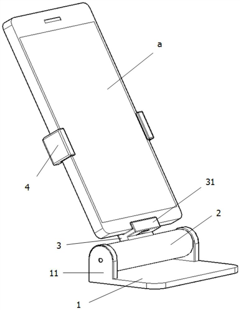
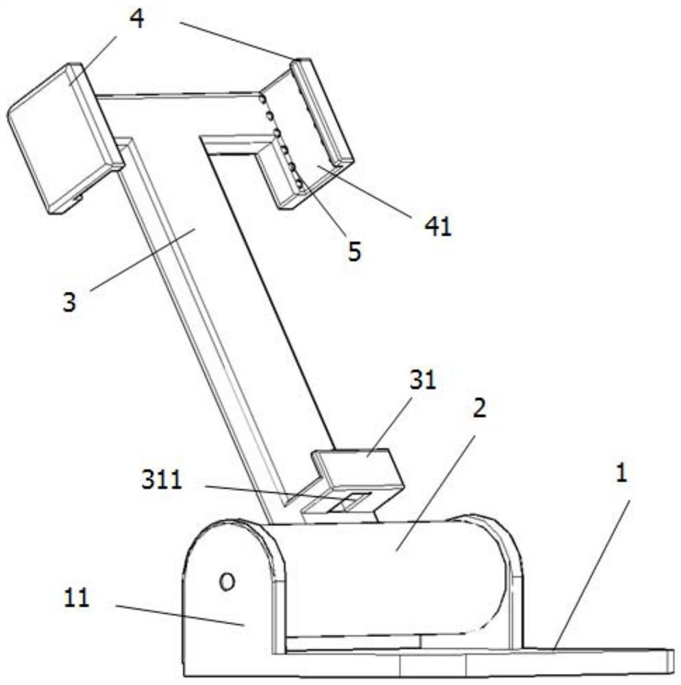
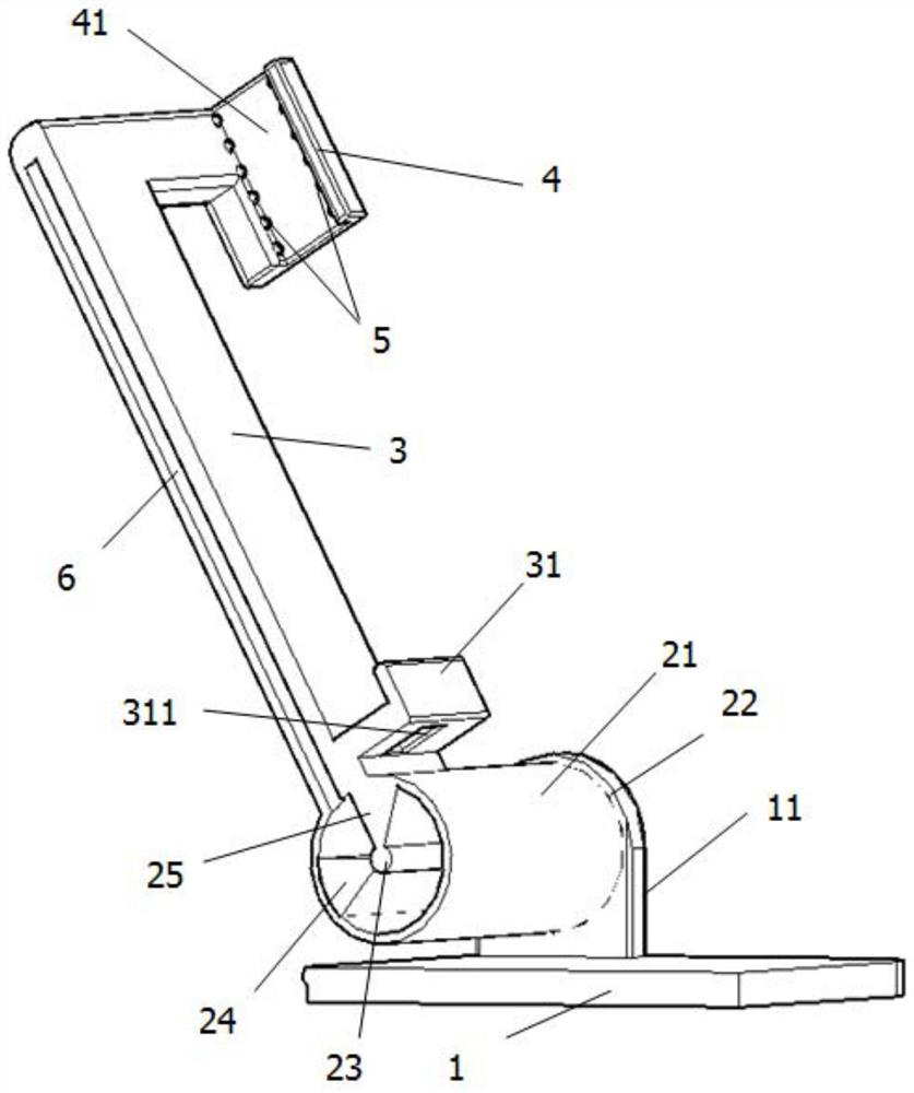
[0029] Such as figure 1 , figure 2 , image 3 As shown, the flip-type pneumatic clamping mobile phone holder includes: a base 1, a rotating cylinder 2, a support arm 3, a chuck 4, a clamping air bag 5, and an air flow channel 6, and one end of the base 1 is arranged upward on both sides There are two support plates 11, the rotary cylinder 2 is erected between the two suppor...


PUM


Abstract

The invention relates to the field of mobile phone auxiliary equipment, and specifically relates to a pneumatic clamping mobile phone holder. The mobile phone holder comprises a base, a rotating cylinder, a supporting arm, a chuck, a clamping air bag and an airflow channel. Two supporting plates are arranged on the two sides of one end of the base upwards. The rotating air cylinder is erected between the two supporting plates. The lower end of the supporting arm is arranged on the peripheral side of the rotary air cylinder. The clamping heads are oppositely arranged on the two sides of the upper end of the supporting arm. U-shaped clamping grooves are formed in the opposite sides of the two clamping heads, the clamping air bags are oppositely arranged along the inner walls of the two sidesof the U-shaped clamping grooves, and the airflow channel is formed in the supporting arm and the clamping heads. One end of the airflow channel is communicated with the rotating air cylinder, and the other end of the airflow channel is communicated with the clamping air bags arranged on the two clamping heads. And the mobile phone can be clamped and locked by inserting and turning over the mobile phone, is turned over reversely, is separated from a clamping and locking state and is easy to take.

Description

technical field [0001] The invention relates to the field of mobile phone auxiliary equipment, in particular to a flip-type pneumatic clamping mobile phone holder. Background technique [0002] The existing car phone holders mainly include magnetic suction type, buckle type and gravity induction type. The magnetic suction mobile phone holder can be used for mobile phones of different sizes, but the disadvantage is that a magnetic sheet needs to be pasted on the back of the mobile phone, which affects the aesthetics of the mobile phone. , the buckle-type mobile phone holder can clamp the mobile phone without auxiliary objects, but the disadvantage is that it needs both hands to complete the operation, which is very inconvenient. The gravity-sensitive mobile phone holder realizes automatic locking through the weight of the mobile phone itself, but the disadvantage is that the mobile phone Its own weight is very small, and it cannot provide enough gravity to automatically lock ...

Claims


Application Information

Patent Timeline
Patent Type & Authority Patents(China)
IPC IPC(8): H04M1/04B60R11/02B60R11/00
CPCB60R11/0241B60R2011/0071H04M1/04
Inventor 陈东海
Owner 安徽冠东科技有限公司
Learn More