Bimetal composite board gluing device

A composite board and bimetallic technology, applied in the field of composite boards, can solve the problems of low efficiency of manual gluing and low product output, and achieve the effect of high degree of automation, high product output, and firm bonding

Inactive Publication Date: 2020-04-07
长兴创智科技有限公司
View PDF0 Cites 3 Cited by
  • Summary
  • Abstract
  • Description
  • Claims
  • Application Information

AI Technical Summary

Problems solved by technology

[0005] The purpose of the present invention is to address the deficiencies of the prior art, realize the transmission of the second composite board by setting the second composite board loading mechanism, and cooperate with the first composite board loading mechanism to realize the transmission of the first composite board, through the second The synchronous transmission of the first composite board and the second composite board realizes precise glue matching to make them fit together, and then uses the pressing component a and the pressing component b to complete the compression of the bimetallic composite board to make the glue more firm. Thus solving the technical problems of low efficiency of artificial glue and low output of products

Method used


Image

  • Bimetal composite board gluing device
  • Bimetal composite board gluing device
  • Bimetal composite board gluing device

Examples


Embodiment 1

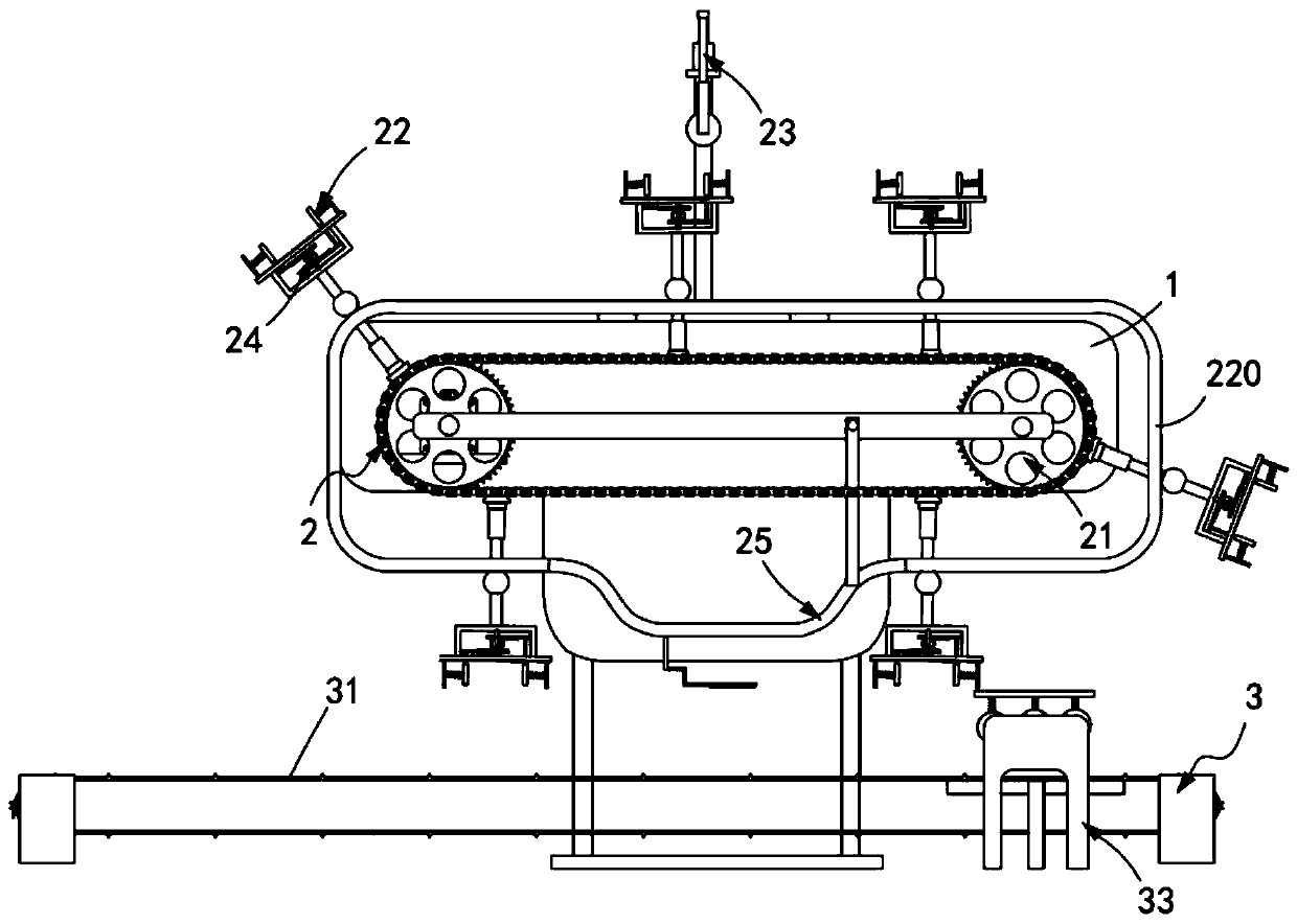
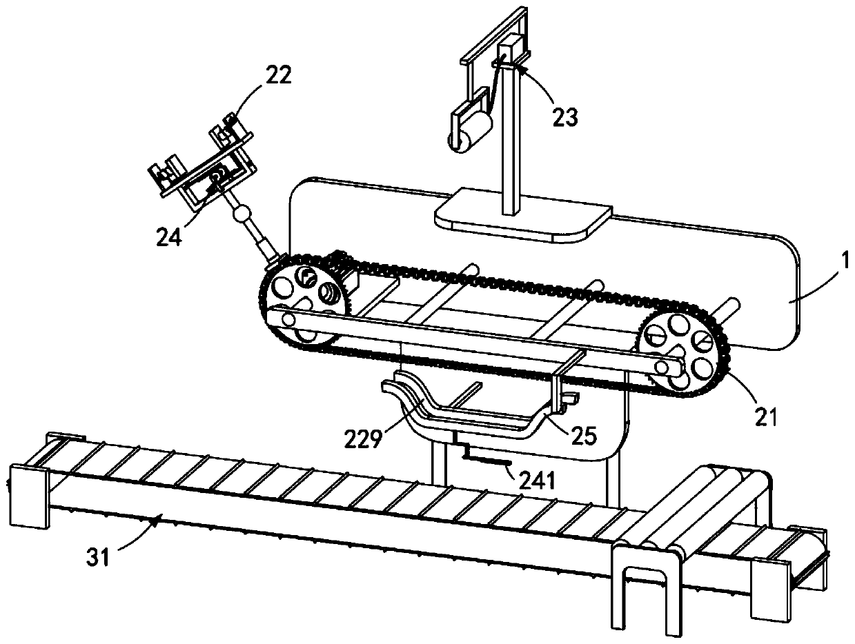
[0043] Such as figure 1 , figure 2 , Figure 10 , Figure 11 with Figure 12 As shown, a bimetal composite board gluing device includes a frame 1, and also includes a first composite board loading mechanism 2 and a second composite board loading mechanism 3 installed on the frame 1, the first composite board The plate mounting mechanism 2 is located above the second composite plate mounting mechanism 3;

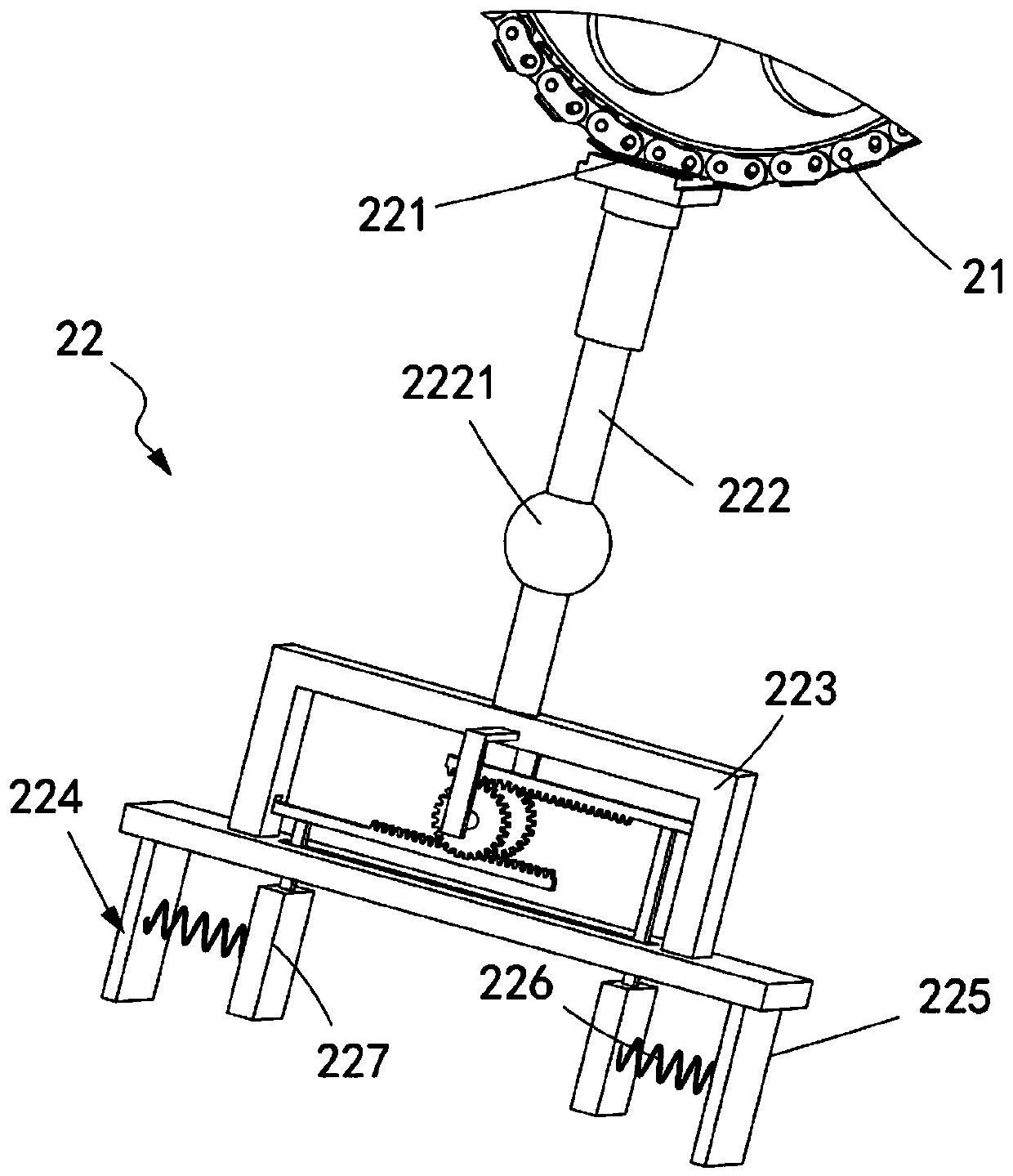
[0044] The first composite plate loading mechanism 2 includes a transmission component a21, a clamping component 22 installed on the transmission component a21, a glue coating component 23 located at one end of the transmission component a21, and a release component that cooperates with the clamping component 22. The release component 24 of the first composite board 10 on the clamping component 22 and the guide component a25 located below the transport component a21; and

[0045] The second composite panel loading mechanism 3 includes a transmission component b31 and a ...

Embodiment 2

[0066] Such as Figure 9 As shown, the components that are the same as or corresponding to those in the first embodiment are marked with the corresponding reference numerals in the first embodiment. For the sake of simplicity, only the differences from the first embodiment will be described below. The difference between this embodiment two and embodiment one is:

[0067] further, such as Figure 9 As shown, the pressing assembly a33 includes a horizontal pressing roller 331 and a telescopic spring 332 elastically connected to the pressing roller 331. The pressing assembly a33 is arranged in several groups along the transmission direction of the transmission assembly b31, and the The thickness from the lower end of the pressing roller 331 to the upper surface of the transmission component b31 is equal to the thickness of the bimetal composite plate 30 .

[0068] Further, a support plate 333 is arranged under the transmission component b31, the transmission component b31 is at...


PUM


Abstract

The invention relates to a bimetal composite board gluing device, which comprises a rack, a first composite board loading mechanism and a second composite board loading mechanism, wherein the first composite board loading mechanism and the second composite board loading mechanism are installed on the rack, the first composite board loading mechanism is located above the second composite board loading mechanism, and comprises a conveying assembly a, a clamping assembly installed on the conveying assembly a, a gluing assembly located at one end of the conveying assembly a, a releasing assembly matched with the clamping assembly and used for releasing a first composite board on the clamping assembly, and a guiding assembly a located below the conveying assembly a, the second composite board loading mechanism comprises a transmission assembly b and a pressing assembly a, and the pressing assembly a performs double-sided pressing in a vertical direction on a adhered bimetal composite board.According to the invention, with the device, the technical problems that the gluing mode cannot achieve the automatic gluing and the automatic output of two composite boards, and the product output quantity is low are solved.

Description

technical field [0001] The invention relates to the technical field of composite boards, in particular to a bimetallic composite board gluing device. Background technique [0002] The base material of the bimetal composite panel usually uses Q235B, Q345B, 20R and other ordinary carbon steel and special steel, and the cladding material can use 304, 316L, 1Cr13 and precious metals such as copper, aluminum, titanium alloy, and the material and thickness can be Free combination to meet the needs of different users. Stainless steel composite panels not only have the corrosion resistance of stainless steel, but also have the good mechanical strength and processing performance of carbon steel. It is a new type of industrial product. Stainless steel composite panels have been widely used in petroleum, chemical, salt, water conservancy and electric power industries. As a resource-saving product, stainless steel composite panels can reduce the consumption of precious metals and greatl...

Claims


Application Information

Patent Timeline
Patent Type & Authority Applications(China)
IPC IPC(8): B32B37/12B32B37/10B32B38/18
CPCB32B37/10B32B37/1284B32B38/18B32B38/1841
Inventor 孙鸿珍
Owner 长兴创智科技有限公司
Why Eureka
Try Eureka