
A pin shaft and a pin shaft reversing device

A technology of reversing device and pin shaft is applied in the directions of transportation and packaging, vibrating conveyor, conveyor objects, etc., which can solve the problems of lack of pin shaft, time-consuming and laborious, troublesome, etc., and achieve the effect of simple and ingenious structure.

Active Publication Date: 2022-05-06
NINGBO SHUAITELONG GRP CO LTD
View PDF8 Cites 0 Cited by
  • Summary
  • Abstract
  • Description
  • Claims
  • Application Information

AI Technical Summary

Problems solved by technology

[0003] Specifically, the existing pin shaft is a cylindrical structure, and both ends are the same, so there is no need to adjust the direction after processing, but some non-cylindrical pins need to be used on some vehicle door handles. The pin shaft with such a special structure is lacking at present
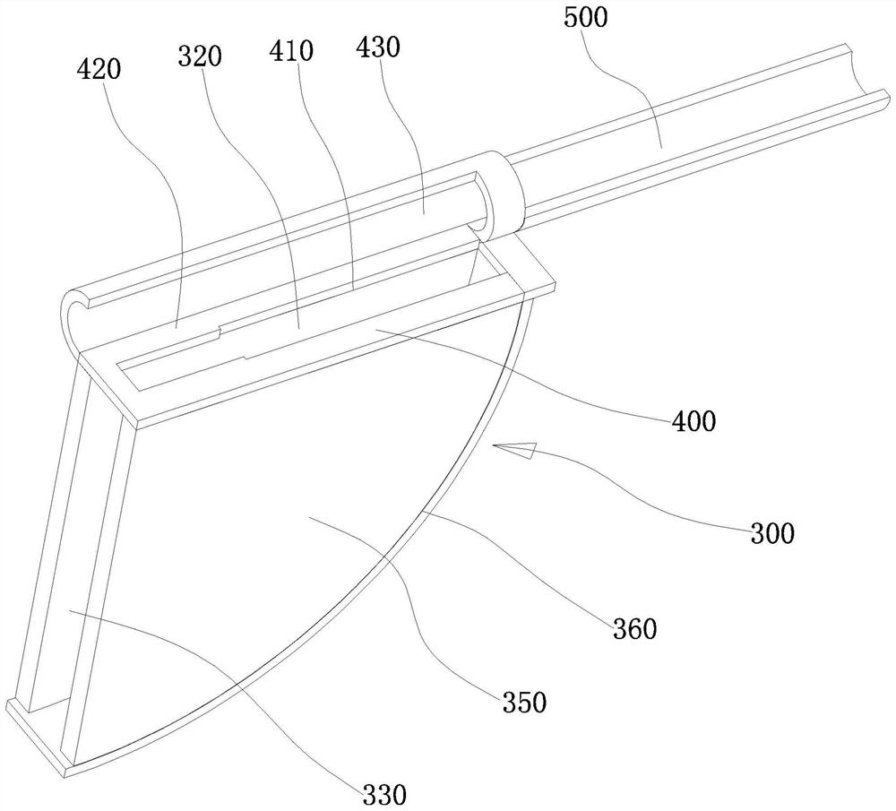
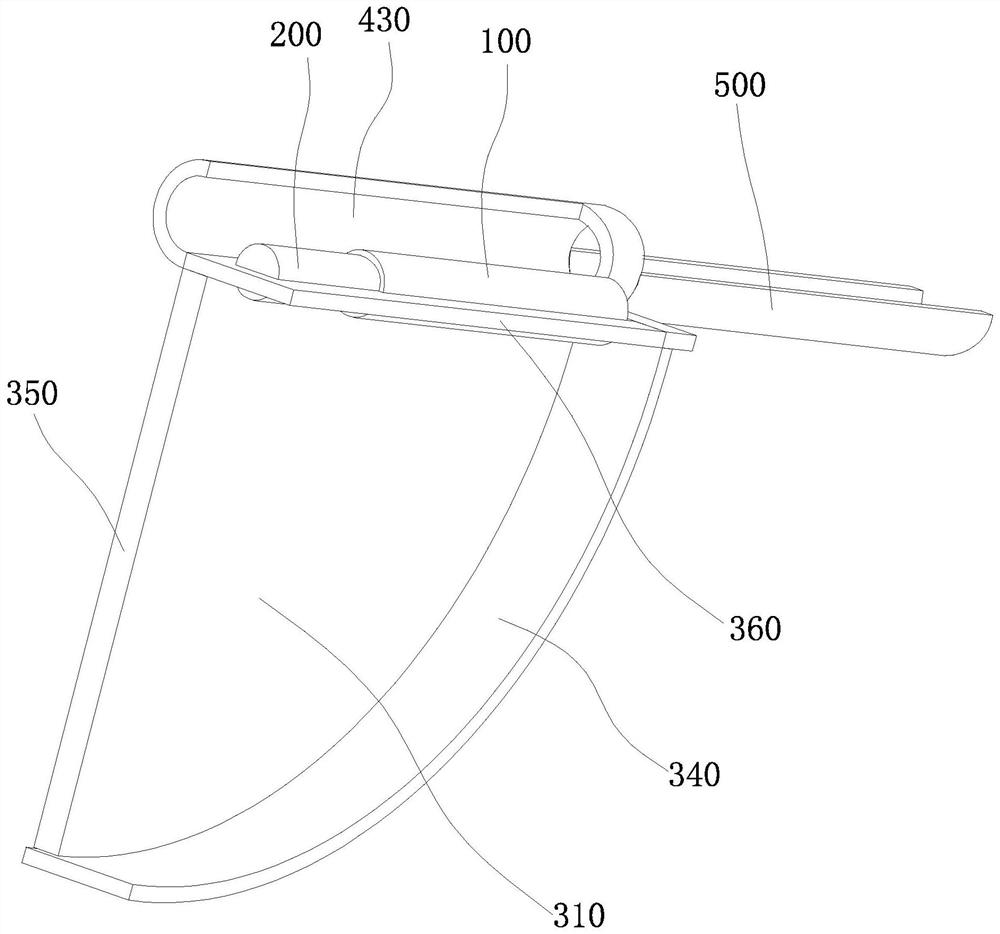
[0004] Moreover, after this kind of pin shaft is manufactured, the diameters of the two ends are different, so one end is the big end and the other end is the small end, and when the pin shaft is assembled on the product, it needs to be arranged for easy access. In production, it is often necessary to sort and arrange manually so that the big end and small end of each pin are arranged in the same way, but this is very troublesome, time-consuming and labor-intensive, so a special device for reversing specific pins is needed

Method used


Image

  • A pin shaft and a pin shaft reversing device
  • A pin shaft and a pin shaft reversing device
  • A pin shaft and a pin shaft reversing device

Examples


Embodiment Construction

[0031] The following are specific embodiments of the present invention and in conjunction with the accompanying drawings, the technical solutions of the present invention are further described, but the present invention is not limited to these embodiments.

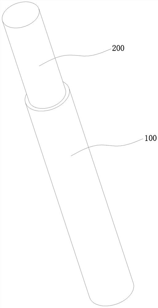
[0032] like figure 2 As shown, a pin shaft includes: a first shaft body 100 and a second shaft body 200, and the first shaft body 100 and the second shaft body 200 are connected to form a stepped shaft structure, which is different from the traditional cylindrical shaft pin In other words, in addition to realizing the hinge function, it also has the effect of axial positioning and support.

[0033] Specifically, the first shaft body 100 has a cylindrical structure, and structures such as knurling can be provided on the first shaft body 100 , and the first shaft body 100 mainly passes through the handle assembly.

[0034] The second shaft body 200 has a cylindrical structure, the end of the second shaft body 200 is connec...


PUM


Abstract

The invention provides a pin shaft, belonging to the technical field of connectors, comprising: a first shaft body, which has a cylindrical structure; a second shaft body, which has a cylindrical structure, and the end of the second shaft body is connected to the The end of the first shaft body is connected, and the first shaft body and the second shaft body are arranged coaxially; a pin shaft reversing device is also provided, which belongs to the technical field of reversing tooling, including: To the seat, it is provided with a conversion chamber, a feed port and a discharge port, and the feed port and the discharge port communicate with the conversion chamber; a screening plate is arranged on the feed port, and the Screening holes are arranged on the screening plate, and the shape of the screening holes is the same as that of the pin shaft. The beneficial effects of the present invention are: providing a stepped pin shaft, and also providing a tool for reversing and arranging the pin shaft in this shape.

Description

technical field [0001] The invention belongs to the technical field of connector technology and reversing tooling thereof, and relates to a pin shaft and a pin shaft reversing device. Background technique [0002] The pin shaft is a commonly used connecting piece, which can be statically fixed or relatively movable with the connected piece. It is mainly used at the hinge of two parts to form a hinge connection. The two ends of the current pin structure are generally The bottom is symmetrical. [0003] Specifically, the existing pin shaft is a cylindrical structure, and both ends are the same, so there is no need to adjust the direction after processing, but some non-cylindrical pins need to be used on some vehicle door handles. The pin shaft of this special structure lacks the pin shaft of this special structure again at present. [0004] Moreover, after this kind of pin shaft is manufactured, the diameters of the two ends are different, so one end is the big end and the o...

Claims


Application Information

Patent Timeline
Patent Type & Authority Patents(China)
IPC IPC(8): B65G47/24B65G47/26B65G27/00
CPCB65G47/24B65G47/26B65G27/00
Inventor 吴志光江华侨刘涛李科炯
Owner NINGBO SHUAITELONG GRP CO LTD
Learn More