
Asphalt waste collection and treatment equipment for road traffic construction

A technology for asphalt waste and road traffic, which is applied in the field of collection and processing equipment, which can solve problems such as damage, violent collision, and poor sealing of equipment, and achieve the effect of accurate scraping work position, avoiding impact damage, and precise working position

Active Publication Date: 2021-08-03
无锡翔云道桥科技有限公司
View PDF6 Cites 0 Cited by
  • Summary
  • Abstract
  • Description
  • Claims
  • Application Information

AI Technical Summary

Problems solved by technology

[0004] The purpose of the present invention is to solve the problem that the existing asphalt waste collection and treatment equipment can cover a small area; the collection and treatment of asphalt waste on the road surface is not comprehensive enough; and the efficiency of the collection and treatment of asphalt waste on the road surface is slow; The waste collection and treatment equipment cannot flexibly adjust the working position and height of the collection parts on the equipment according to the road surface with different slopes, which not only leads to low working accuracy of the equipment, but also causes the collection parts on the equipment to easily contact with the ground when it is moving. Violent collisions of protrusions lead to damage; asphalt waste collection and processing equipment makes a lot of noise when it is working; when collecting asphalt waste, asphalt waste is easy to spill out from the equipment, and the sealing of the equipment is poor; In view of the problem of low loading capacity, a kind of asphalt waste collection and treatment equipment for road traffic construction is proposed

Method used


Image

  • Asphalt waste collection and treatment equipment for road traffic construction
  • Asphalt waste collection and treatment equipment for road traffic construction
  • Asphalt waste collection and treatment equipment for road traffic construction

Examples


Embodiment Construction

[0045] The technical solutions of the present invention will be clearly and completely described below in conjunction with the embodiments. Apparently, the described embodiments are only some of the embodiments of the present invention, not all of them. Based on the embodiments of the present invention, all other embodiments obtained by persons of ordinary skill in the art without creative efforts fall within the protection scope of the present invention.

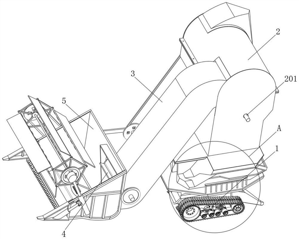
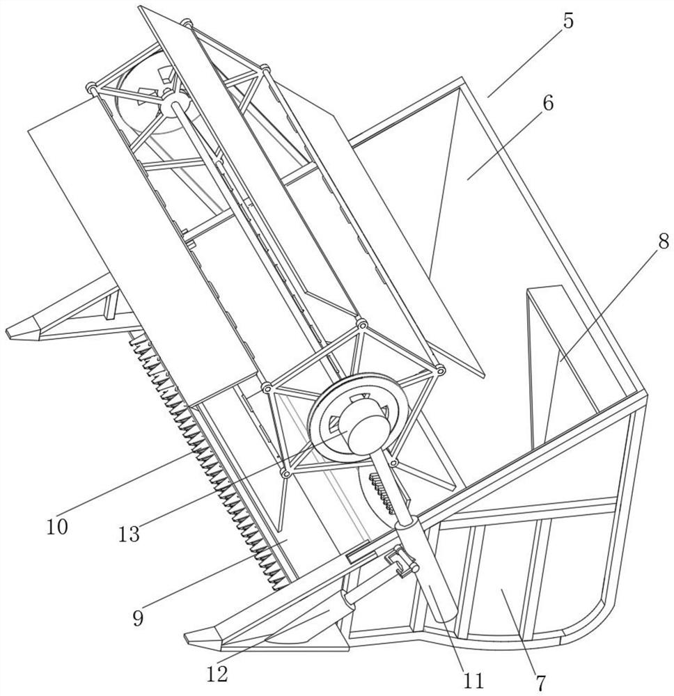
[0046] see Figure 1-11 As shown, a kind of asphalt waste collection and treatment equipment for road traffic construction, including engine 1, charging box 2 of hollow structure, inner sleeve 3, feeding tray 4 and collecting tray 5, charging box 2 is vertically arranged on The top of the engine 1 and the top of the charging box 2 are provided with a stirring seat 201. One end of the charging box 2 is obliquely provided with an inner sleeve 3, and the inner sleeve 3 is provided with a feeding tray 4, and the bottom of the i...


PUM


Abstract

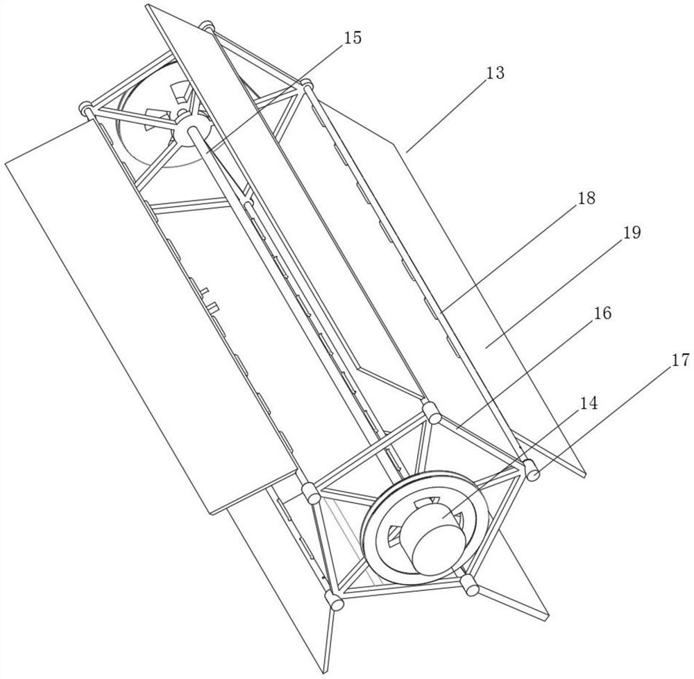
The invention discloses an asphalt waste collection and treatment equipment for road traffic construction, which comprises an engine, a hollow structure charging box, an inner sleeve, a material delivery tray and a collection tray, the charging box is vertically arranged above the engine, And the top of the charging box is set with a stirring seat, one end of the charging box is obliquely provided with an inner sleeve, and the inner sleeve is provided with a feeding tray, and one end of the bottom of the inner sleeve is provided with a collection tray. The beneficial effect of the present invention is that: during the moving process of the equipment, the asphalt waste on the road surface is shoveled into the shovel loading bucket, and the motor on the scraper frame drives the pentagonal frame and the scraper plate to rotate through the rotating shaft. Five scraping plates rotate to scrape the asphalt waste on the road into the collection tray. On the one hand, it ensures that the equipment collects the asphalt on the road more comprehensively and thoroughly. On the other hand, it cooperates with the equipment to collect asphalt waste in a mobile manner Work, greatly improving the efficiency of the equipment for collecting asphalt waste.

Description

technical field [0001] The invention relates to collection and treatment equipment, in particular to asphalt waste collection and treatment equipment for road traffic construction, and belongs to the technical field of application of asphalt waste collection and treatment equipment. Background technique [0002] After road traffic construction, a large amount of asphalt waste will be left on the road surface. The main function of the asphalt waste collection and treatment equipment is to collect and store the asphalt waste on the road surface in a unified manner, which is convenient for later recycling and reuse of asphalt waste, and ensures the safety of the road surface. cleanliness. [0003] There are still many deficiencies in the existing asphalt waste collection and treatment equipment in use. The existing asphalt waste collection and treatment equipment can cover a small area when working, and the collection and treatment of asphalt waste on the road surface is not co...

Claims


Application Information

Patent Timeline
Patent Type & Authority Patents(China)
IPC IPC(8): E01C23/12E01C23/06
CPCE01C23/065E01C23/124
Inventor 沈美莲
Owner 无锡翔云道桥科技有限公司
Learn More