
Side plate structure and dehumidifier with the same

A dehumidifier and side plate technology, applied in the field of side plate structure and dehumidifiers with it, can solve the problems of air leakage of the dehumidifier and affect the working efficiency of the dehumidifier, and achieve the effect of improving work efficiency and user experience

Pending Publication Date: 2020-04-07
GREE ELECTRIC APPLIANCES INC
View PDF0 Cites 0 Cited by
  • Summary
  • Abstract
  • Description
  • Claims
  • Application Information

AI Technical Summary

Problems solved by technology

[0004] The main purpose of the present invention is to provide a side plate structure and a dehumidifier with it, so as to solve the problem in the prior art that the dehumidifier is prone to air leakage and affects the working efficiency of the dehumidifier

Method used


Image

  • Side plate structure and dehumidifier with the same
  • Side plate structure and dehumidifier with the same
  • Side plate structure and dehumidifier with the same

Examples


Embodiment Construction

[0026] It should be noted that, in the case of no conflict, the embodiments in the present application and the features in the embodiments can be combined with each other. The present invention will be described in detail below with reference to the accompanying drawings and examples.

[0027] It should be noted that, unless otherwise specified, all technical and scientific terms used in this application have the same meaning as commonly understood by those of ordinary skill in the art to which this application belongs.

[0028] In the present invention, in the absence of a contrary statement, the used orientation words such as "up and down" usually refer to the direction shown in the drawings, or refer to the vertical, vertical or gravity direction Similarly, for the convenience of understanding and description, "left and right" usually refer to the left and right shown in the drawings; The words are not used to limit the invention.

[0029] In order to solve the problem in...


PUM


Abstract

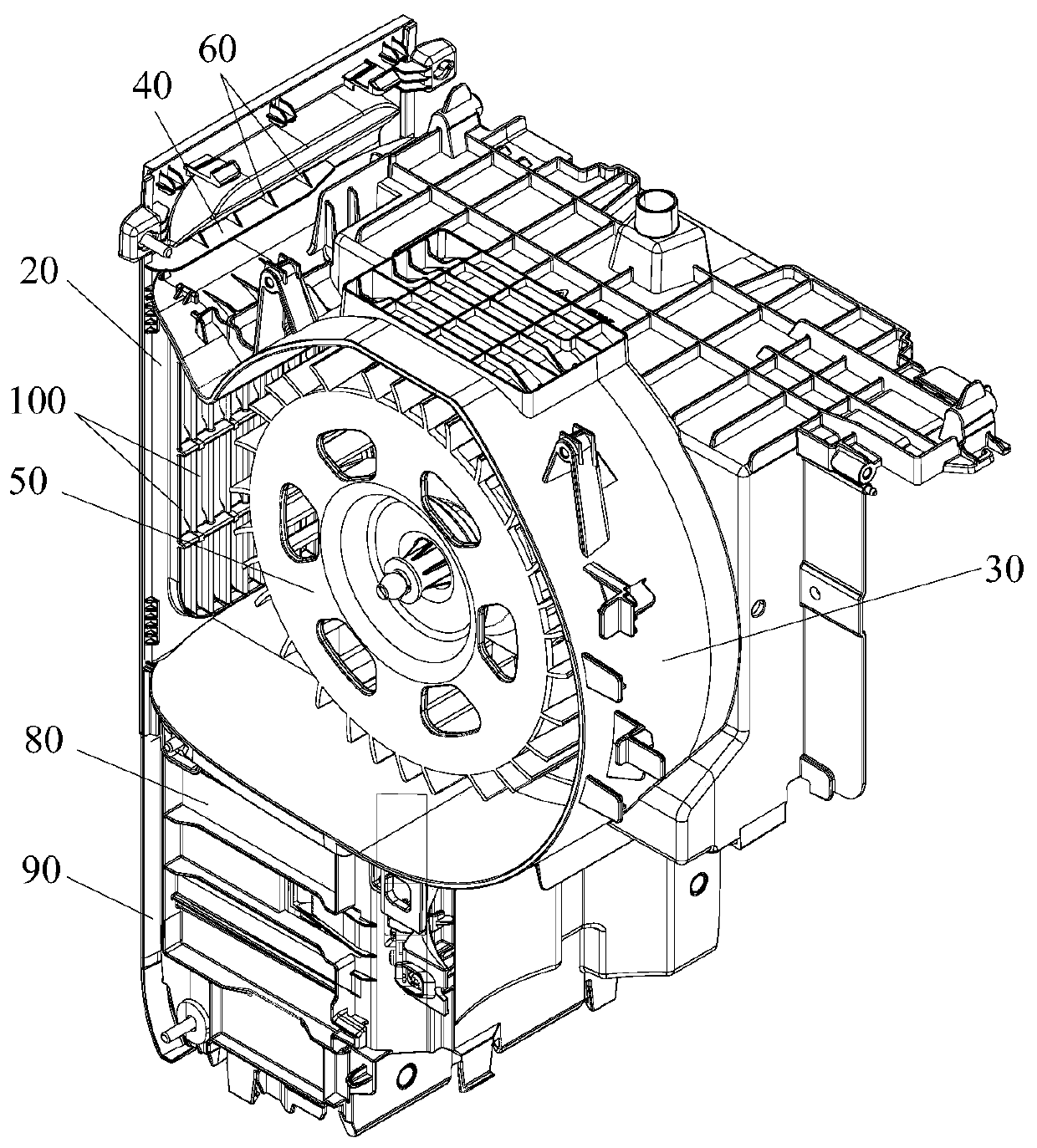
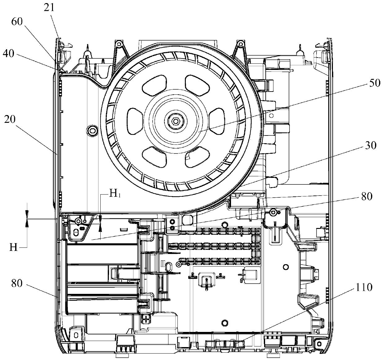
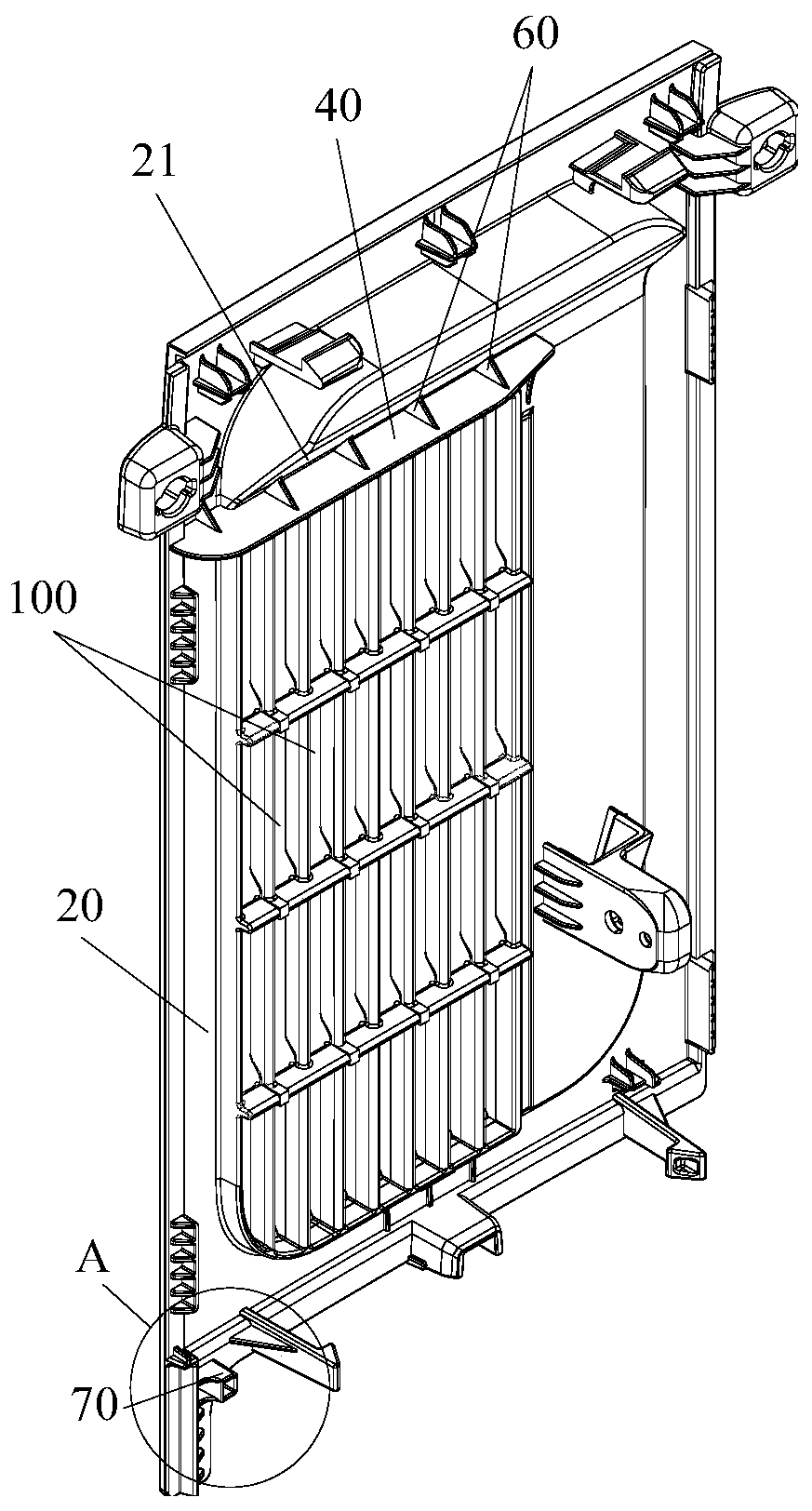
The invention provides a side plate structure and a dehumidifier with the same. The side plate structure is used for being connected with a dehumidifier shell of the dehumidifier. The side plate structure comprises a side plate body and an extending portion, wherein a gap is formed between an end portion, facing towards the side plate body, of a flow guide ring of the dehumidifier and the side plate body; and the extending portion is arranged on the side plate body, and the extending portion extends towards the dehumidifier shell so as to block the gap. In the invention, a problem that in theprior art, working efficiency of the dehumidifier is affected due to a fact that the dehumidifier is easy to generate air leakage is effectively solved.

Description

technical field [0001] The invention relates to the technical field of dehumidifiers, in particular to a side plate structure and a dehumidifier having the same. Background technique [0002] At present, household dehumidifiers have been widely used. They can adjust the indoor temperature, play a good role in moisture-proof and mildew-proof, and can also speed up the drying of clothes. [0003] However, during the operation of the dehumidifier, due to the gap between the guide ring and the side plate, the airflow blown from the fan passes through the above gap to the outside of the dehumidifier, resulting in air leakage, which affects the working efficiency of the dehumidifier and the use of users. experience. Contents of the invention [0004] The main purpose of the present invention is to provide a side plate structure and a dehumidifier with it, so as to solve the problem in the prior art that the dehumidifier is prone to air leakage and affects the working efficiency...

Claims


Application Information

Patent Timeline
Patent Type & Authority Applications(China)
IPC IPC(8): F24F13/20F24F3/14
CPCF24F3/14F24F13/20
Inventor 汤志平鞠文宏胡树锋郝树坤吴永昌李杰
Owner GREE ELECTRIC APPLIANCES INC
Learn More