Auxiliary welding equipment for cylindrical foundation column steel bars

An auxiliary welding and steel bar technology, applied in auxiliary welding equipment, welding equipment, welding/cutting auxiliary equipment, etc., can solve the problems of affecting the welding effect, not being able to fix round steel bars and long steel bars, and affecting work efficiency

Active Publication Date: 2020-04-10
NANJING YUQUN COMM TECH CO LTD
View PDF10 Cites 2 Cited by
  • Summary
  • Abstract
  • Description
  • Claims
  • Application Information

AI Technical Summary

Problems solved by technology

[0005] In order to overcome the shortcomings that the circular steel bar and the long steel bar cannot be fixed manually during welding, which affects the welding effect, and the distance between the two long steel bars needs to be manually measured during welding, which affects the work efficiency. The technical problem of the present invention is to provide An auxiliary welding equipment for cylindrical foundation construction steel bars that can fix round steel bars and long steel bars during welding and ensure work efficiency

Method used


Image

  • Auxiliary welding equipment for cylindrical foundation column steel bars
  • Auxiliary welding equipment for cylindrical foundation column steel bars
  • Auxiliary welding equipment for cylindrical foundation column steel bars

Examples


Embodiment 1

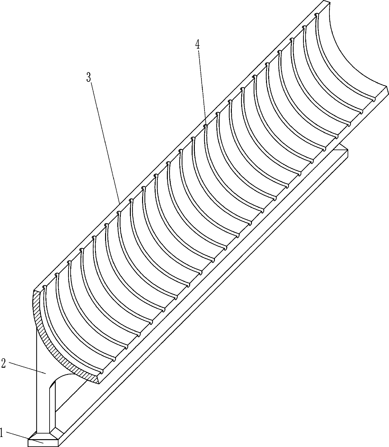
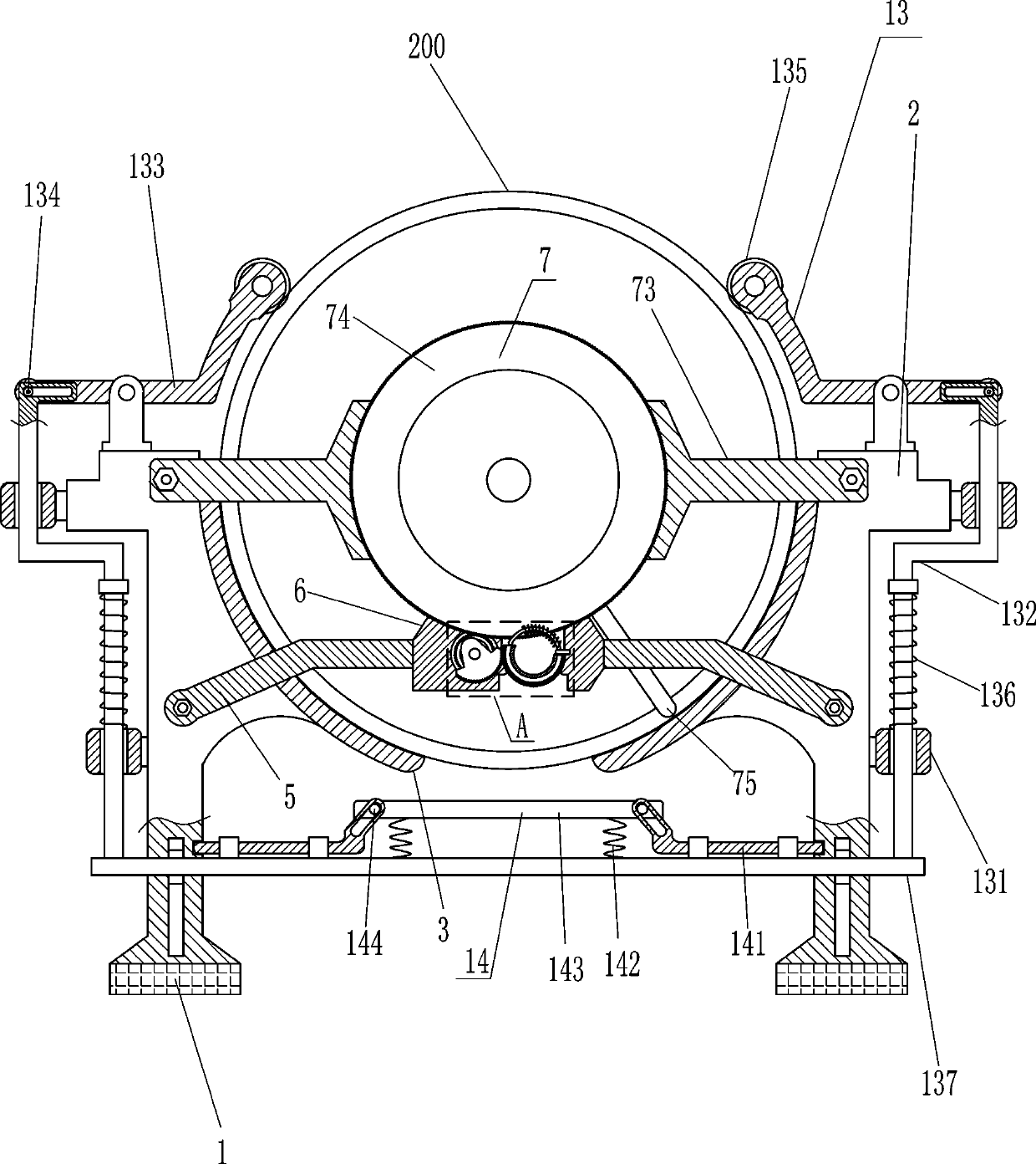
[0019] Refer to 1-2, an auxiliary welding equipment for cylindrical foundation building steel bars, including a base 1, a bracket 2 and a curved plate 3, the tops of the two bases 1 are connected to the front and rear sides of the bracket 2, and the bracket 2 and the base 1 pass through Connected by means of bolt connection, the brackets 2 on both sides are provided with arc-shaped plates 3, and the two arc-shaped plates 3 form an unconnected semicircle, and the arc-shaped plates 3 are evenly spaced with arc-shaped grooves 4. The width of 4 is slightly greater than the diameter of the steel ring, and also includes connecting frame 5, fixed plate 6 and rotating assembly 7, and the front and rear walls of both sides of support 2 are provided with connecting frame 5, and bolts are used between connecting frame 5 and support 2 The connecting frame 5 is located at the lower part of the arc-shaped plate 3, and the two connecting frames 5 at the front and rear are connected with a fix...

Embodiment 2

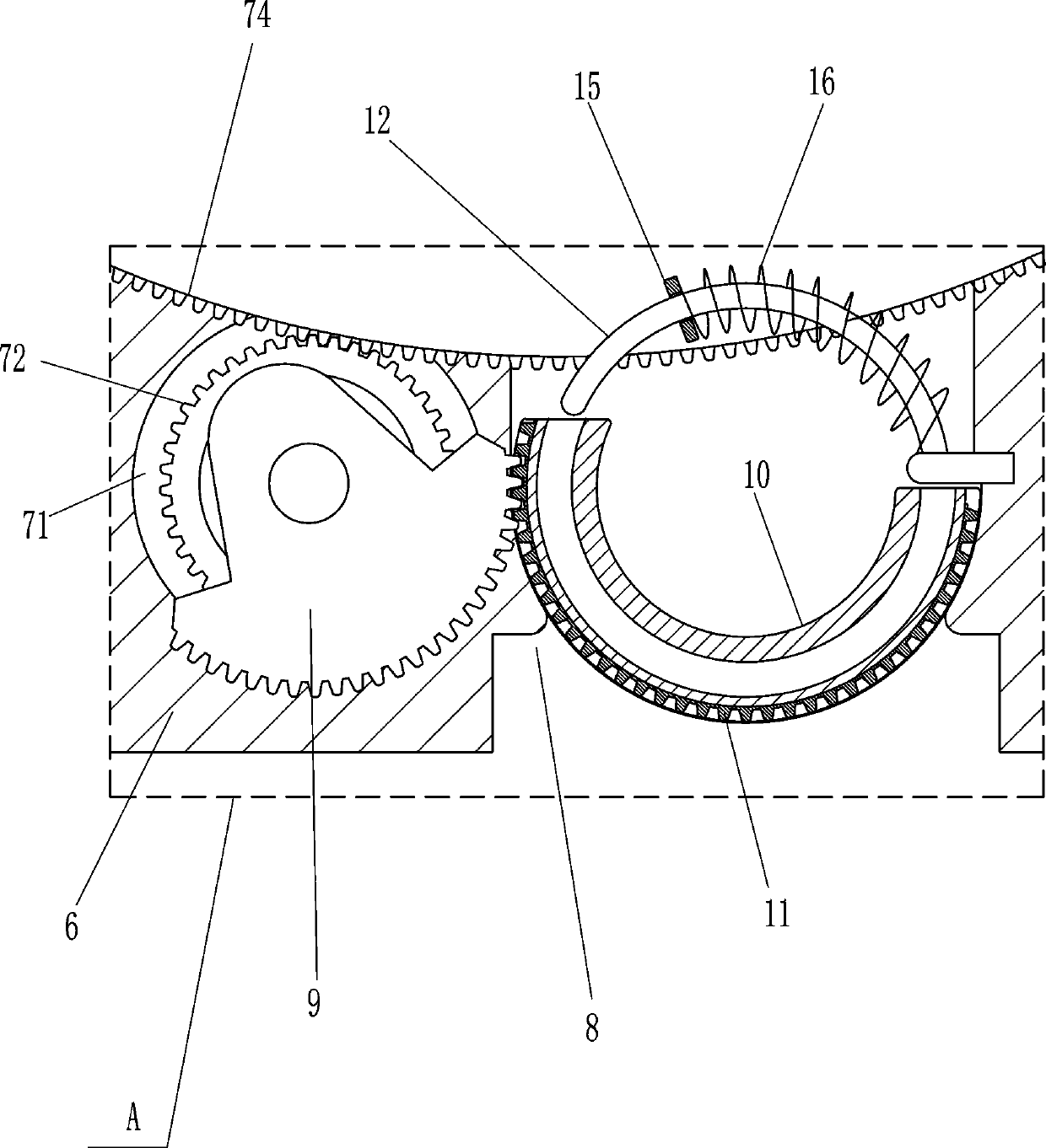
[0024] Referring to 3, it also includes a sector gear 9, an arc tube 10, an arc rack 11 and an arc guide rod 12. The middle part of the fixed plate 6 is provided with a placement groove 8, and the placement groove 8 is an arc shape with upper and lower openings. Gear 72 front end face is connected with sector gear 9, is placed with arc pipe 10 in placing groove 8, and arc pipe 10 can rotate in placing groove, and arc pipe 10 outer surface is provided with arc rack 11, and arc rack 11 is embedded on the arc tube 10, the arc rack 11 meshes with the sector gear 9, the upper part of the placement groove 8 is provided with an arc guide rod 12, and the arc guide rod 12 is connected to the fixed plate 6. There is a chute cooperating with the arc-shaped guide rod 12 inside the tube 10, and the arc-shaped tube 10 is slidably matched with the arc-shaped guide rod 12 through the chute.

[0025] When it is necessary to place a long steel bar, the arc tube 10 is placed between the insides ...

Embodiment 3

[0027] refer to figure 1 , also includes a fixed assembly 13, the fixed assembly 13 includes a guide sleeve 131, a first sliding rod 132, a swing rod 133, a first roller 134, a pressure wheel 135, a first compression spring 136 and a connecting rod 137, and the brackets on both sides 2 The front and rear sides of the outer wall are provided with guide sleeves 131, and the first sliding rod 132 is slid inside the guide sleeve 131. The shape of the first sliding rod 132 is a side "Z" shape, and the top of the first sliding rod 132 has a guide Slot, the guide groove is arranged horizontally, the front and rear sides of both sides support 2 tops are all hingedly connected with swing lever 133, and swing lever 133 one end is provided with first roller 134, and first roller 134 is positioned at guide groove, and swing lever 133 The other end is rotatably provided with a pinch roller 135 for pressing the steel bar ring, which is a rotary connection between the pinch wheel 135 and the...


PUM


Abstract

The invention relates to auxiliary welding equipment, and particularly relates to an auxiliary welding equipment for cylindrical foundation column steel bars. The technical problem of the auxiliary welding equipment is how to design the auxiliary welding equipment for the cylindrical foundation column steel bars capable of fixing the circular steel bars and the long-strip-shaped steel bars duringwelding and ensuring the work efficiency. The auxiliary welding equipment for the cylindrical foundation column steel bars comprises a base, supports, arc-shaped plates, connecting frames and the like; the supports are connected to the front and rear sides of the tops of the two bases, the arc-shaped plates are arranged in the supports on the two sides, the two arc-shaped plates form a semi-circlewhich is not connected, arc-shaped grooves are uniformly formed in the arc-shaped plates at intervals, and the connecting frames are arranged on front walls and rear walls of the supports on two sides, and the connecting frames are located on the lower portions of the arc-shaped plates. According to the auxiliary welding equipment, firstly, steel bar rings are placed in the arc-shaped grooves onthe arc-shaped plates, then the long-strip-shaped steel bars are placed in the steel bar rings, and the steel bar rings are limited through the cooperation of a fixing assembly and a clamping assembly, therefore, and the problem that the steel bar rings are moved out of the arc-shaped grooves during welding can be avoided.

Description

technical field [0001] The invention relates to an auxiliary welding equipment, in particular to an auxiliary welding equipment for cylindrical foundation building steel bars. Background technique [0002] With the continuous development of the construction industry in modern society and the improvement of people's living standards, many large buildings in modern society have many thick columns. This kind of column has a strong load-bearing capacity and can be used as a frame column. Due to the effects of compression and earthquake resistance, this kind of column needs to weld many round steel bars and long steel bars together to form the base column reinforcement, and then pour concrete into the base column reinforcement to form the column. [0003] At present, the welding method of the foundation column reinforcement is generally to place the round steel bar and the long steel bar together for welding. Because it is difficult to fix the round steel bar and the long steel b...

Claims


Application Information

Patent Timeline
Patent Type & Authority Applications(China)
IPC IPC(8): B23K37/04
CPCB23K37/04B23K37/0443
Inventor 钟海星
Owner NANJING YUQUN COMM TECH CO LTD
Why Eureka
Try Eureka