

An attitude-orbit coupling control method and system thereof
A coupling control and attitude-orbit technology, applied in the aerospace field, can solve the problems of tight structure installation space, complex system, and increased number of pipeline joints, and achieve the effect of simplifying hardware and system design
- Summary
- Abstract
- Description
- Claims
- Application Information
AI Technical Summary
Problems solved by technology
Method used
Image

Examples
Embodiment Construction
[0027] The technical solutions in the embodiments of the present invention are clearly and completely described below in conjunction with the accompanying drawings in the embodiments of the present invention. Obviously, the described embodiments are part of the embodiments of the present invention, but not all of them. Based on the embodiments of the present invention, all other embodiments obtained by those skilled in the art without making creative efforts belong to the protection scope of the present invention.
[0028] The present application provides an attitude-orbit coupling control method and its system, which have the technical effects of simplifying system design, improving system reliability and reducing system risk.
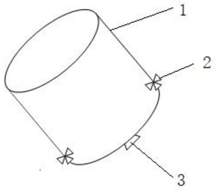
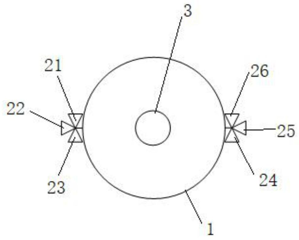
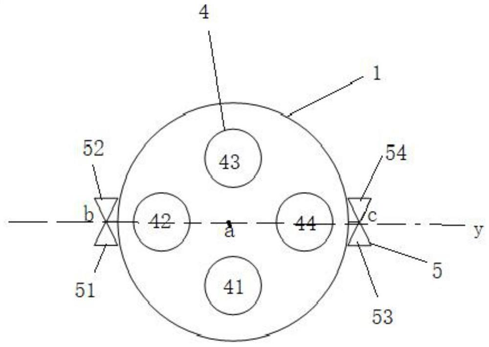
[0029] Such as image 3 , Figure 4 with Figure 5 As shown, the present application provides an attitude-orbit coupling control system, which includes a carrier body 1, multiple engines 4, multiple nozzles 5, a controller, and a delivery system. W...
PUM
 Abstract
Description
Claims
Application Information