Novel air inlet nozzle runner and air column bag

A technology of air inlet nozzle and air column bag, which is applied in the field of new air inlet nozzle flow channel and air column bag, which can solve the problems of high production cost, heat sealing failure, insufficient air pressure, etc., and achieve air tightness and heat sealing effect Effect

Pending Publication Date: 2020-04-10
HANGZHOU BINGJIA TECH
View PDF0 Cites 0 Cited by
  • Summary
  • Abstract
  • Description
  • Claims
  • Application Information

AI Technical Summary

Problems solved by technology

At present, most of the air column bags on the market use the inlet flow channel of the one-way valve. The advantages of this kind of air column bag are: after the high-pressure gas rushes into the air column bag, no heat sealing is required, and the gas will not leak in the opposite direction, thus Realize sealing, but the disadvantages are: 1. The area of ​​the one-way valve is a three-layer film, which requires more materials and higher cost, and the production cost is higher due to the authorization fee of the one-way valve patent; 2. The structure of the one-way valve It can lock the gas, but if it is placed for a long time (such as 3~6 months), the gas will slowly leak from the one-way valve, resulting in insufficient internal air pressure
The disadvantage of this air intake nozzle structure is that high-pressure gas has been rushed into the body of the air column bag during pressing and heat sealing. After the heat sealing is completed, the pressing force disappears. The gas will break the heat-sealed upper and lower layers of film, resulting in heat-sealing failure

Method used


Image

  • Novel air inlet nozzle runner and air column bag
  • Novel air inlet nozzle runner and air column bag
  • Novel air inlet nozzle runner and air column bag

Examples


Embodiment 1

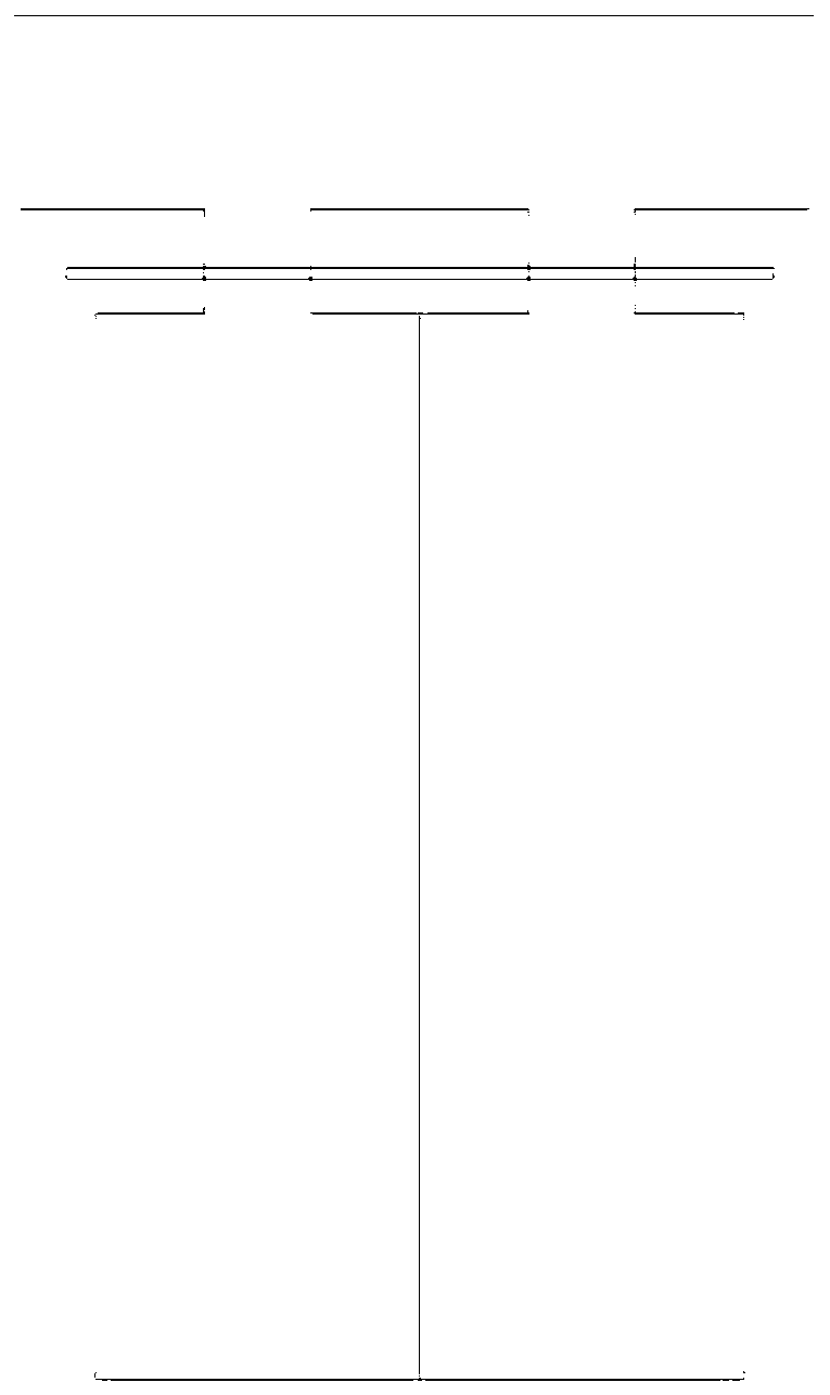
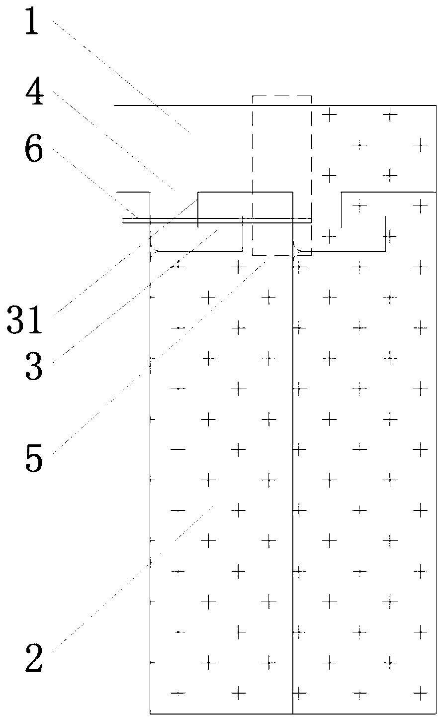
[0030] An air column bag with an air inlet flow path, comprising an air inlet channel 1 formed by heat sealing of upper and lower films and a plurality of air column bag units 2. The air inlet flow path 3 includes an inlet 4 and an outlet 5. The air inlet The inlet 4 and outlet 5 of the runner 3 are respectively connected to the air inlet channel 1 and the air column bag unit 2, and the air inlet runner 3 is separated by a sealing line 31 to form two right-angle bends, such as figure 2 As shown, during the heat sealing process, after the inlet 4 area is heat-sealed, the heat-sealing pressing area (rectangular frame in the figure) moves to the right. At this time, the high-pressure gas is still locked in the right area, and the gas will not affect the inlet 4 The heat-sealing line 6 at the location is affected, and the heat-sealing line 6 begins to cool. When the hot-pressing zone moves to the right of the outlet 5 area, the high-pressure gas will flow through the inlet nozzle ru...

Embodiment 2

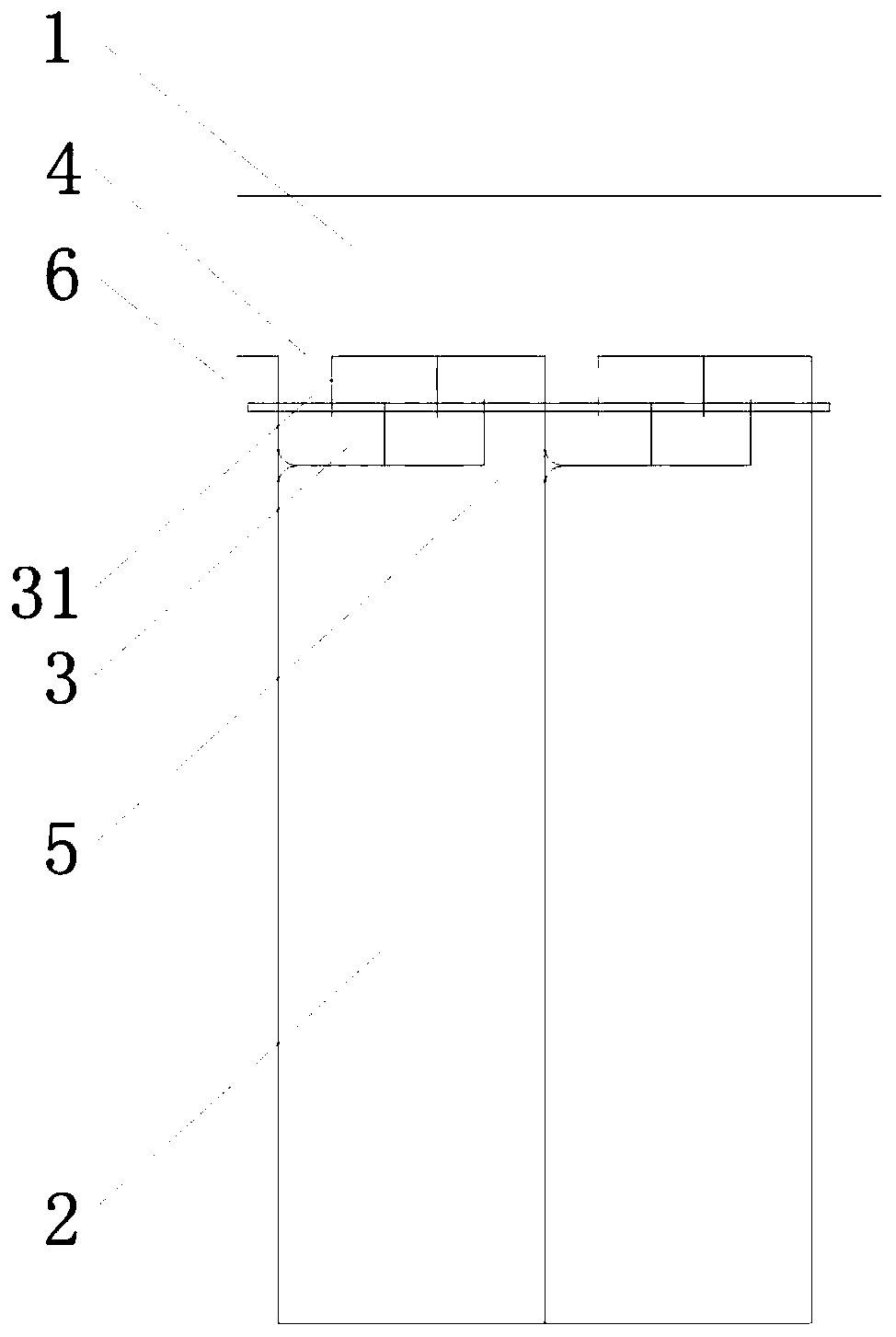
[0032] The difference between this embodiment and embodiment 1 is that the inlet nozzle runner 3 is separated by the sealing line 31 to form 4 right-angle bends, such as image 3 As shown, by increasing the number of bends, the effect of blocking high-pressure gas is more obvious.

Embodiment 3

[0034] The difference between this embodiment and embodiment 1 is that the angle of the curve is greater than 90 degrees, such as Figure 4 Shown.


PUM


Abstract

The invention discloses a novel air inlet nozzle runner and an air column bag. The air inlet nozzle runner comprises an inlet and an outlet. The air inlet nozzle runner is divided by sealing lines toform a plurality of bends. The air column bag comprises the air inlet nozzle runner and further comprises an air inlet channel formed by heat sealing of an upper membrane and a lower membrane and a plurality of air column bag units. The inlet and the outlet of the air inlet nozzle runner communicate with the air inlet channel and the air column bag units respectively. The novel air inlet nozzle runner has the advantages of being good in airtightness and stable in heat sealing effect.

Description

Technical field [0001] The invention belongs to the technical field of air intake runners, and specifically relates to a novel air intake nozzle runner and air column bag. Background technique [0002] Air column bags, also known as cushioning air column bags, inflatable bags, bubble column bags, and cylindrical inflatable bags, are new packaging materials filled with natural air. At present, most of the gas cylinder bags on the market use the inlet flow channel of the one-way valve. The advantage of this gas cylinder bag is: after high-pressure gas is flushed into the gas cylinder bag, heat sealing is not required, and the gas will not leak in the reverse direction. To achieve sealing, but the disadvantages are: 1. The one-way valve area is a three-layer film, which requires more materials and higher costs, and the production cost is higher due to the licensing fee of the one-way valve patent; 2. The structure of the one-way valve It can lock the gas, but if it is placed for a ...

Claims


Application Information

Patent Timeline
Patent Type & Authority Applications(China)
IPC IPC(8): B65D81/05
CPCB65D81/052
Inventor 刘玉贵
Owner HANGZHOU BINGJIA TECH
Why Eureka
Try Eureka