Overspeed brake device of rubber belt conveyor

A belt conveyor and brake device technology, which is applied in the direction of conveyor, transportation and packaging, etc., can solve the problems of belt conveyor overspeed, achieve the effect of simple control, stable structure, and eliminate potential safety hazards

Inactive Publication Date: 2020-04-10
SHANDONG LINENG LUXI MINING IND CO LTD
View PDF9 Cites 0 Cited by
  • Summary
  • Abstract
  • Description
  • Claims
  • Application Information

AI Technical Summary

Problems solved by technology

When the belt conveyor is overspeed, pull the control valve to realize the contraction of the pneumatic device, and the cylinder contraction of the pneumatic device drives the upper movable brake device to approach the lower fixed brake device, and the upper movable brake device and the lower fixed brake device cooperate to clamp the lower belt to realize conveying The deceleration of the belt effectively solves the problem that the electric roller belt conveyor transports coal gangue when the tunnel is headed up the mountain, and when the coal gangue is loaded too much, the belt conveyor will run at an excessive speed.

Method used


Image

  • Overspeed brake device of rubber belt conveyor
  • Overspeed brake device of rubber belt conveyor
  • Overspeed brake device of rubber belt conveyor

Examples


Embodiment 1

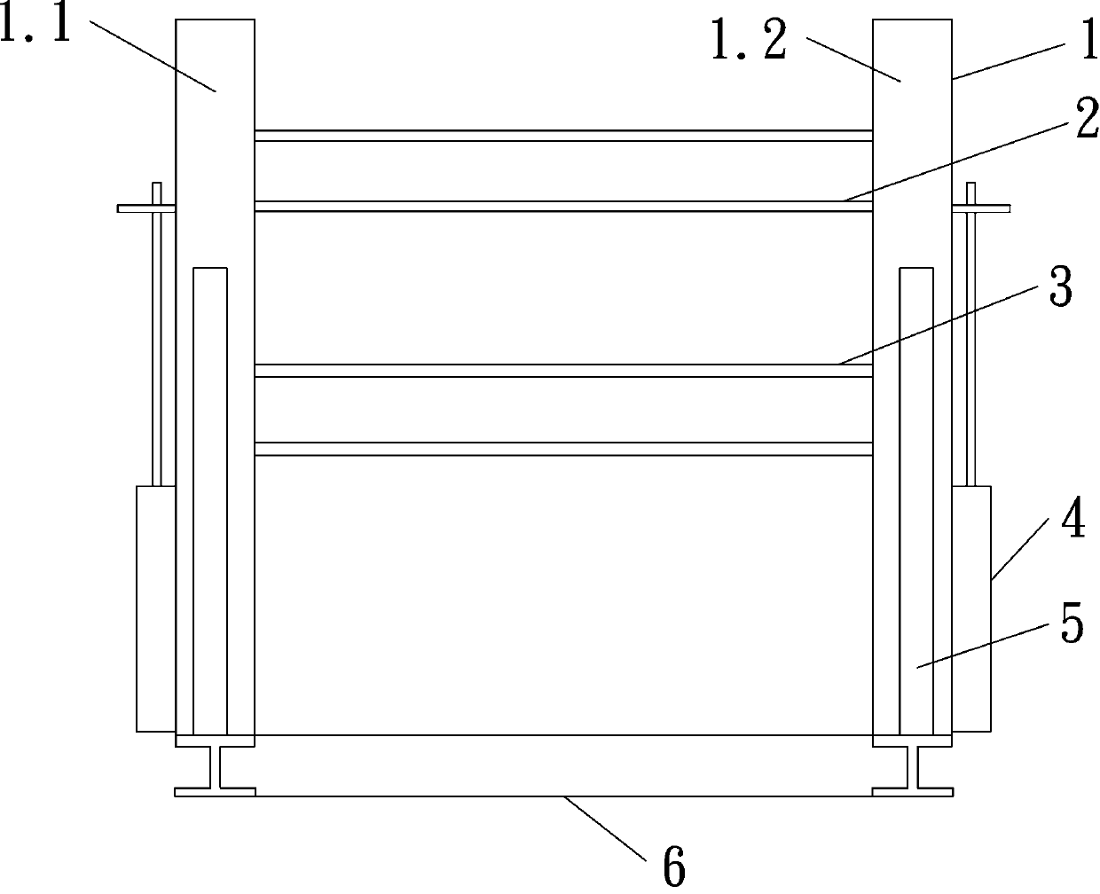
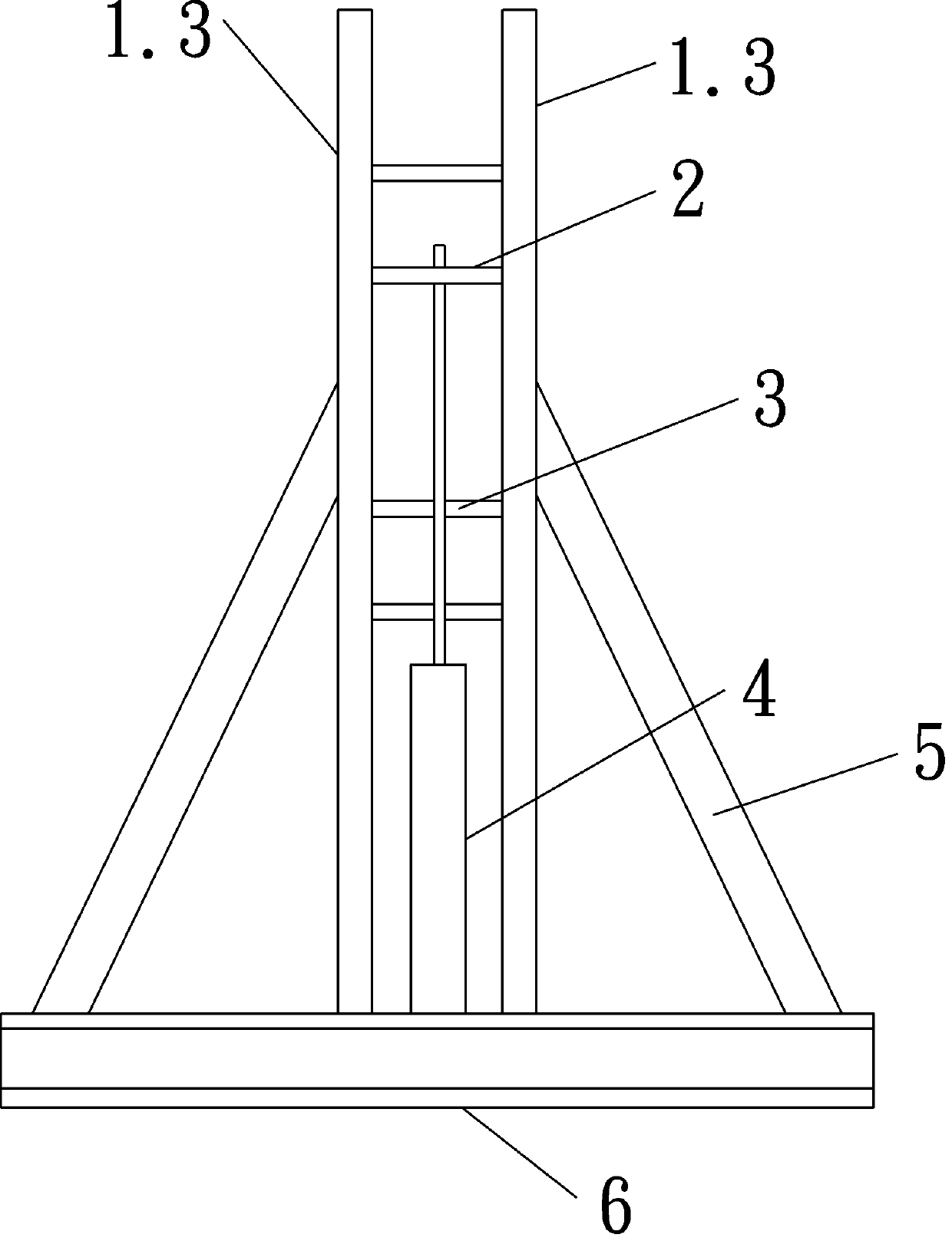
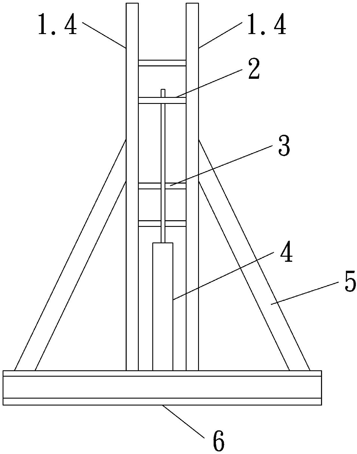
[0041] Such as Figure 1-3 As shown, the belt conveyor overspeed braking device includes a frame body 1, an upper movable brake device 2 is installed on the upper part of the frame body 1, a lower fixed brake device 3 is installed on the lower part of the frame body 1, and a movable brake device 3 is installed on the upper part of the frame body 1. The device 2 and the lower fixed brake device 3 are arranged opposite to each other. When the upper movable brake device 2 and the lower fixed brake device 3 are close to each other, they can squeeze the lower adhesive tape, and then apply a certain pre-pressure. The pneumatic device 4 is also included, and the pneumatic device 4 can Drive the upper movable brake device 2 to approach or move away from the lower fixed brake device 3. When the belt conveyor is overspeed, pull the control valve to realize the contraction of the pneumatic device 4, and the contraction of the cylinder of the pneumatic device 4 drives the upper movable bra...

Embodiment 2

[0043] Embodiment two, such as Figure 4-8 As shown, the difference from Embodiment 1 is that the pneumatic device 4 is replaced by a clamping cylinder 7.5, which also includes a fixed guide 7, and the upper movable brake device 2 is made of I-shaped steel, which includes ribs Plate one 2.2 and the first upper wing plate 2.1 and the second lower wing plate 2.3 vertically connected to the rib plate one 2.2, the first upper wing plate 2.1 and the second lower wing plate 2.3 are parallel to the lower adhesive tape, and They are respectively arranged at both ends of the first rib plate 2.2, and the second lower wing plate 2.3 is located above the lower adhesive tape. The fixed guide 7 includes an outer casing 7.1 with a rectangular cross-section and openings at both ends. The lower part of the outer casing 7.1 Along its length, the surface is provided with a long hole 7.3 for the rib plate 1 2.2 to pass through, and a vertical guide side plate 7.2 is respectively arranged on the t...


PUM


Abstract

The invention relates to an overspeed brake device of a rubber belt conveyor. The device comprises a frame body, wherein an upper movable brake device is installed on the upper portion of the frame body, a lower fixed brake device is installed on the lower portion of the frame body, the upper movable brake device and the lower fixed brake device are oppositely arranged, when the upper movable brake device and the lower fixed brake device are close to each other, a lower-layer rubber belt can be extruded, certain pre-pressure is further applied, and the overspeed brake device comprises a pneumatic device, and the pneumatic device can drive the upper movable brake device to be close to or away from the lower fixed brake device. The overspeed brake device has the following beneficial effectsthat when the rubber belt conveyor overspeeds, the upper movable brake device and the lower fixed brake device cooperate to clamp the lower-layer rubber belt, speed reduction of the conveying belt isachieved, and the problem that during tunnelling face raise construction, an electric roller belt conveyor transports coal gangue, and overspeed operation of the rubber belt conveyor can be caused when the coal gangue is excessively loaded is effectively solved.

Description

technical field [0001] The invention relates to an overspeed braking device of a belt conveyor, which belongs to the technical field of belt conveyor transportation of coal gangue. Background technique [0002] Belt conveyor is the most commonly used conveying equipment. When excavating uphill with a large inclination angle, electric roller belt conveyor is needed to transport coal gangue. Due to the strong effect of natural gravity, excessive loading of coal gangue will cause the belt conveyor to overspeed. running problem. On the one hand, the overspeed operation of the belt conveyor will cause serious piles of coal gangue at the belt head, crushing the lower belt; on the other hand, it may cause mechanical and electrical equipment accidents or property losses. Contents of the invention [0003] According to the deficiencies in the prior art above, the technical problem to be solved by the present invention is: in order to solve one of the above problems, an overspeed b...

Claims


Application Information

Patent Timeline
Patent Type & Authority Applications(China)
IPC IPC(8): B65G23/26
CPCB65G23/26
Inventor 张涛时维玉李善祥蒋春光辛海亭季勇
Owner SHANDONG LINENG LUXI MINING IND CO LTD
Why Eureka
Try Eureka