High load jet bridge device

A high-load, jet outlet technology, applied in bridges, floating bridges, bridge forms, etc., can solve the problems of long construction period and high erection cost, and achieve the effects of low cost, high bearing capacity and strong practicability

Active Publication Date: 2021-07-02
SHENZHEN ZHU GUANGBO MACHINERY TECH
View PDF7 Cites 0 Cited by
  • Summary
  • Abstract
  • Description
  • Claims
  • Application Information

AI Technical Summary

Problems solved by technology

Bridge erection costs are high and construction period is long

Method used


Image

  • High load jet bridge device
  • High load jet bridge device
  • High load jet bridge device

Examples


Embodiment Construction

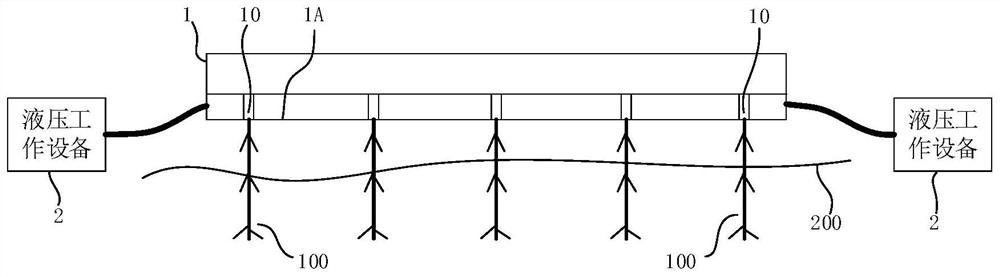
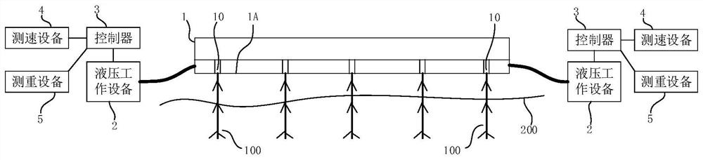
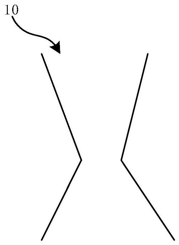
[0029] In order to make the technical problems, technical solutions and beneficial effects to be solved by the embodiments of the present application clearer, the following combination Figure 1 to Figure 7 And embodiment, this application is described in further detail. It should be understood that the specific embodiments described here are only used to explain the present application, not to limit the present application.

[0030] It is to be understood that the terms "length", "width", "top", "bottom", "front", "rear", "left", "right", "vertical", "horizontal", "top" , "bottom", "inner", "outer" and other indicated orientations or positional relationships are based on the orientations or positional relationships shown in the drawings, and are only for the convenience of describing the embodiments of the present application and simplifying the description, rather than indicating or implying Any device or element must have a specific orientation, be constructed, and operate...


PUM


Abstract

The embodiment of the present application discloses a high-load jet bridge device, which includes a bridge main body and hydraulic working equipment; at least one bottom surface of the bridge main body is provided with a plurality of jet outlets; the hydraulic working equipment is used to provide the jet outlet with High-pressure liquid, so that the liquid is ejected from the jet outlet to form a high-pressure columnar liquid. The high-load jet bridge device of the embodiment of the present application can bear a large mass, has a high load-bearing capacity, is easy to build quickly, has strong practicability, and is low in cost.

Description

technical field [0001] The present application relates to the technical field of fluid mechanics, in particular to a high-load jet bridge device. Background technique [0002] A bridge is a link of connection. The bridge plays a role of smooth connection on some roads that cannot continue. The bridge is generally composed of piers, approach bridges and bridge decks, and the piers support knocking; or set suspended objects on the water surface to support the bridge surface. The erection cost of the bridge is high and the construction period is long. [0003] The disclosure of the above background technical content is only used to assist in understanding the inventive concepts and technical solutions of this application, and it does not necessarily belong to the prior art of this application. In the absence of clear evidence that the above content has been disclosed on the filing date of this application Under such circumstances, the above background technology should not b...

Claims


Application Information

Patent Timeline
Patent Type & Authority Patents(China)
IPC IPC(8): E01D15/14
CPCE01D15/14
Inventor 朱光波刘喜灵
Owner SHENZHEN ZHU GUANGBO MACHINERY TECH
Why Eureka
Try Eureka