Self-adaptive anti-collision door handle
A door handle and self-adaptive technology, applied in the field of door handles, can solve problems such as crashes
- Summary
- Abstract
- Description
- Claims
- Application Information
AI Technical Summary
Problems solved by technology
Method used
Image

Examples
Embodiment 1
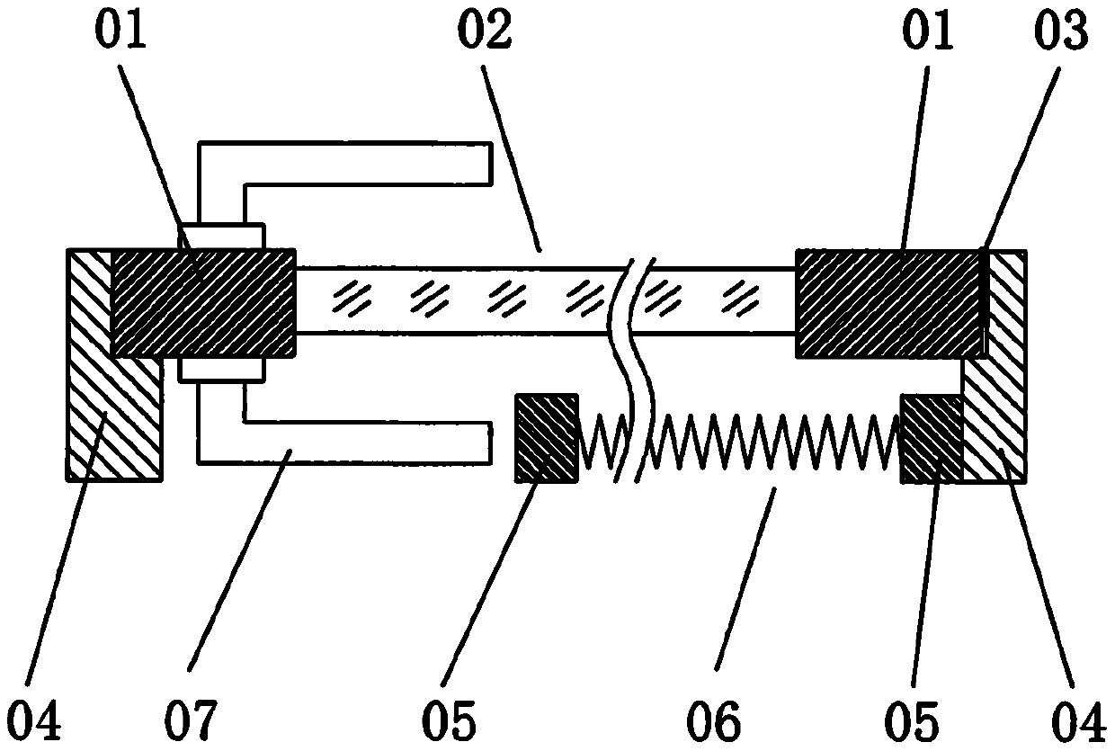
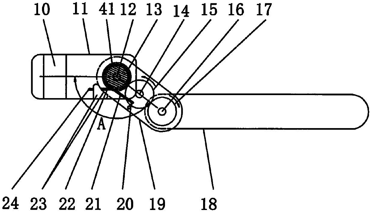
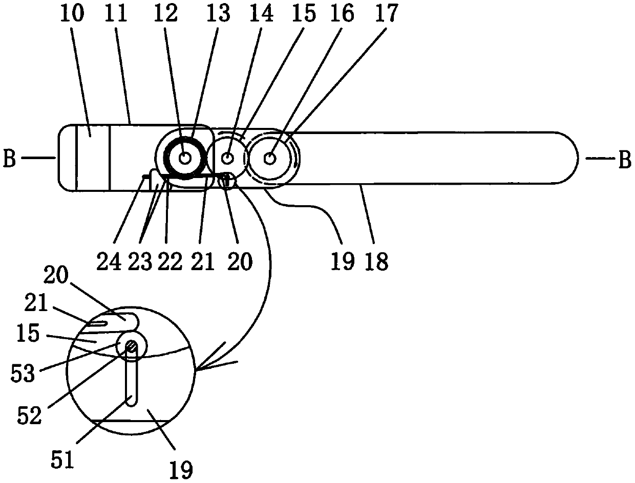
[0024] Embodiment 1: Adaptive anti-collision door handle, including a rocker arm 11 with a lock shaft installation hole 10 or a lock shaft installation groove at one end, and the other end of the rocker arm 11 passes through the connection between the first pin shaft 12 and the connecting rod 19 One end is hinged, and the other end of the connecting rod 19 is hinged with the handle through the second bearing pin 16. The first torsion spring 41 that drives the connecting rod 19 to rotate to one side is installed on the first bearing pin 12. The other end of the rocker arm 11 and one end of the connecting rod 19 are provided with a limiting structure 23 that limits the rotation angle of the connecting rod 19 .
[0025] One end 22 of the first torsion spring 41 is limited on the slot 24 of the rocker arm 11 , and the other end 21 is limited on the slot 20 of the connecting rod 19 .
[0026] The limit structure 23 for limiting the rotation angle of the connecting rod 19 may be a l...
Embodiment 2
[0035] Embodiment 2: Adaptive anti-collision door handle, including a rocker arm 11 with a lock shaft installation hole 10 or a lock shaft installation groove at one end, and the other end of the rocker arm 11 passes through the first pin shaft 12 and one end of the connecting rod 19 Hinged, the other end of the connecting rod 19 is hinged with the handle through the second pin shaft 16, the first torsion spring 41 that drives the connecting rod 19 to rotate to one side is installed on the first pin shaft 12, the rocker The other end of the arm 11 and one end of the connecting rod 19 are provided with a limiting structure 23 that limits the rotation angle of the connecting rod 19 .
[0036] One end of the first torsion spring 41 is limited on the rocker arm 11 , and the other end is limited on the connecting rod 19 .
[0037] The limit structure 23 for limiting the rotation angle of the connecting rod 19 may be a limit block cooperating with the side wall of the connecting rod, ...
PUM
 Abstract
Description
Claims
Application Information
 - Generate Ideas
- Intellectual Property
- Life Sciences
- Materials
- Tech Scout
- Unparalleled Data Quality
- Higher Quality Content
- 60% Fewer Hallucinations
Browse by: Latest US Patents, China's latest patents, Technical Efficacy Thesaurus, Application Domain, Technology Topic, Popular Technical Reports.
© 2025 PatSnap. All rights reserved.Legal|Privacy policy|Modern Slavery Act Transparency Statement|Sitemap|About US| Contact US: help@patsnap.com