Long-distance vertical floating support shafting structure

A floating support, long-distance technology, applied in the direction of bearing components, shafts and bearings, rigid supports of bearing components, etc., can solve the problems of poor rotor dynamic performance, material waste, etc., and achieve the effect of reducing vibration problems

Active Publication Date: 2020-04-10
XIAN PUMP & VALVE GENERAL FACTORY CO LTD
View PDF11 Cites 0 Cited by
  • Summary
  • Abstract
  • Description
  • Claims
  • Application Information

AI Technical Summary

Problems solved by technology

[0005] The purpose of the present invention is to provide a long-distance vertical floating support shafting structure. By setting a positioning adjustment mechanism and a floating support structure, the short shaft structure ensures stable transmission with the working section and is not affected by the front end. The long shaft sh

Method used


Image

  • Long-distance vertical floating support shafting structure
  • Long-distance vertical floating support shafting structure
  • Long-distance vertical floating support shafting structure

Examples


Embodiment 1

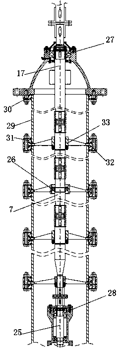
[0040] Please refer to Figure 1-4 As shown, a long-distance vertical floating support shafting structure includes a positioning adjustment structure 27, a number of floating support structures 26 and a short shaft structure 28, and also includes a first shaft 17, a number of second shafts 7 and a third shaft 25 , the first shaft 17, several second shafts 7 and the third shaft 25 are sequentially connected, and the several second shafts 7 are connected end-to-end, the positioning adjustment structure 27 is sleeved on the first shaft 17, and the positioning adjustment structure 27 drives the first The first shaft 17 moves in the axial direction of the first shaft 17, the short shaft structure 28 is sleeved on the third shaft 25, and the short shaft structure 28 and the third shaft 25 are relatively stationary in the axial direction of the third shaft 25; The floating support structure 26 includes a rolling bearing 4, a bearing floating sleeve 3, a sliding key 6 and a floating b...

Embodiment 2

[0051] Please refer to Figure 1-4 As shown, this embodiment optimizes the design of the positioning adjustment structure 27 to achieve a better positioning adjustment effect.

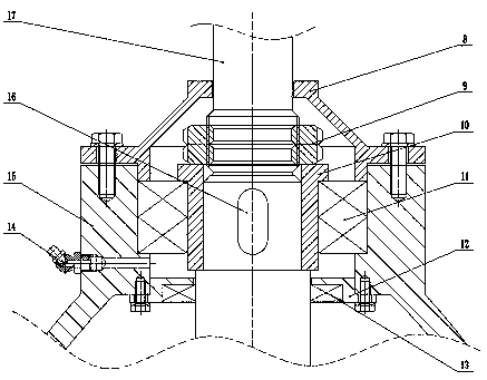
[0052] In the example, as image 3 As shown, the positioning adjustment structure 27 includes a first thrust bearing 11, a shaft sleeve 10 and a bearing housing 15. The shaft sleeve 10 is sleeved on the first shaft 17, and the first thrust bearing 11 is sleeved on the shaft sleeve 10. The outer ring of the first thrust bearing 11 is stationary relative to the bearing housing 15, and the inner ring of the first thrust bearing 11 is stationary relative to the shaft sleeve 10. The positioning adjustment structure 27 also includes an adjusting nut 9, which is sleeved on the first shaft. 17 , the adjusting nut 9 is located on the end surface of the sleeve 10 , and the adjusting nut 9 drives the first shaft 17 to move in the axial direction of the first shaft 17 relative to the axial direction. The adjustm...

Embodiment 3

[0058] Please refer to Figure 1-4 As shown, the present embodiment optimizes the design of the floating support structure 26 to achieve a better restriction and use effect on the second shaft 7 .

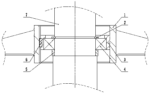
[0059] Such as figure 2 As shown, in this embodiment, the floating support structure 26 includes a rolling bearing 4, a bearing floating sleeve 3, a sliding key 6 and a floating bearing bracket 1, and several rolling bearings 4 are sleeved on a second shaft 7, and each second shaft 7 There is at least one rolling bearing 4, the inner ring of the rolling bearing 4 is relatively stationary to the second shaft 7, the bearing floating sleeve 3 is set on the outer ring of the rolling bearing 4, the bearing floating sleeve 3 and the outer ring of the rolling bearing 4 are relatively stationary, and the bearing floating sleeve 3 is connected with the sliding key 6, and the floating bearing bracket 1 is provided with a sliding groove, and the sliding key 6 and the sliding groove are nested...


PUM


Abstract

The invention provides a long-distance vertical floating support shafting structure, and the structure is used for supporting a large-span slender shaft and is characterized in that an adjusting and positioning structure with an adjusting function is adopted at the top, and an upper adjusting structure, a middle limiting structure and a bottom fixing structure are formed, so a stable shaft transmission structure is formed; the quick assembly and sealing protection on an inner shaft are achieved by arranging a split type shell outside the structure; and the split type shell is also convenient for bracket installation of the floating support structure and the sliding guide bearing structure. According to rotor dynamics, one or more rolling bearing structures capable of axially floating are matched with the position, needing to be limited, of shafting rotation deformation, so the deformation and vibration during shafting operation are limited, and the problems that the shafting cannot work normally due to long shaft accumulative machining errors, assembling and centering difficulties and the like are solved.

Description

technical field [0001] The invention relates to the field of mechanical transmission, in particular to a long-distance vertical floating support shaft system structure. Background technique [0002] The vertical long-axis transmission structure is mostly used in vertical systems where the size of the horizontal space structure is limited and the power source is located in the vertical direction of the mechanical structure. It has the characteristics of small footprint, no need to reserve a large area for installation, controlling the prime mover to achieve long-distance operation, etc. [0003] The traditional vertical long-shaft shafting structure has a thick shaft diameter and serious waste of materials. Especially in the transmission with long shafting, it is difficult to guarantee the processing quality, assembly quality, etc., the adjustability is poor, the tolerance is poor, the requirements for parts are high, and there is no compensation structure, which affects the...

Claims


Application Information

Patent Timeline
IPC IPC(8): F16C35/08F16C35/10F16C35/12
CPCF16C35/08F16C35/10F16C35/12
Inventor 谷帅坤魏清希
Owner XIAN PUMP & VALVE GENERAL FACTORY CO LTD
Why Eureka
Try Eureka