Direct current charging cable for charging automobile

A technology for DC charging and charging cars, which is applied in the field of cables and car charging cables. It can solve the problems of inconvenient adjustment of cable length, simple external structure, and poor storage effect, and achieve stable storage, high flexibility, and convenient storage. Effect

Pending Publication Date: 2022-07-29
广东坚宝电缆有限公司
View PDF0 Cites 0 Cited by
  • Summary
  • Abstract
  • Description
  • Claims
  • Application Information

AI Technical Summary

Problems solved by technology

[0002] With the continuous development of society, the development and utilization of new energy has gradually entered the society, including electric vehicles. Electric vehicles refer to vehicles powered by vehicle-mounted power supplies, driven by motors, and meeting the requirements of road traffic and safety regulations. Vehicles, and in the use of charging cars, we need to use charging cables. The current DC charging cables for charging cars are basically simple connecting cables. Although the internal structure is relatively mature, the external structure is too simple, and it is still in actual use. It is inconvenient to adjust the length of the cable, and it is not easy to store. A small number of cables with storage function have poor storage effect, damage to the inner core of the cable, and poor functionality. Therefore, we propose an optimized and improved charging system. DC Charging Cables for Automobiles

Method used


Image

  • Direct current charging cable for charging automobile
  • Direct current charging cable for charging automobile
  • Direct current charging cable for charging automobile

Examples


Embodiment 1

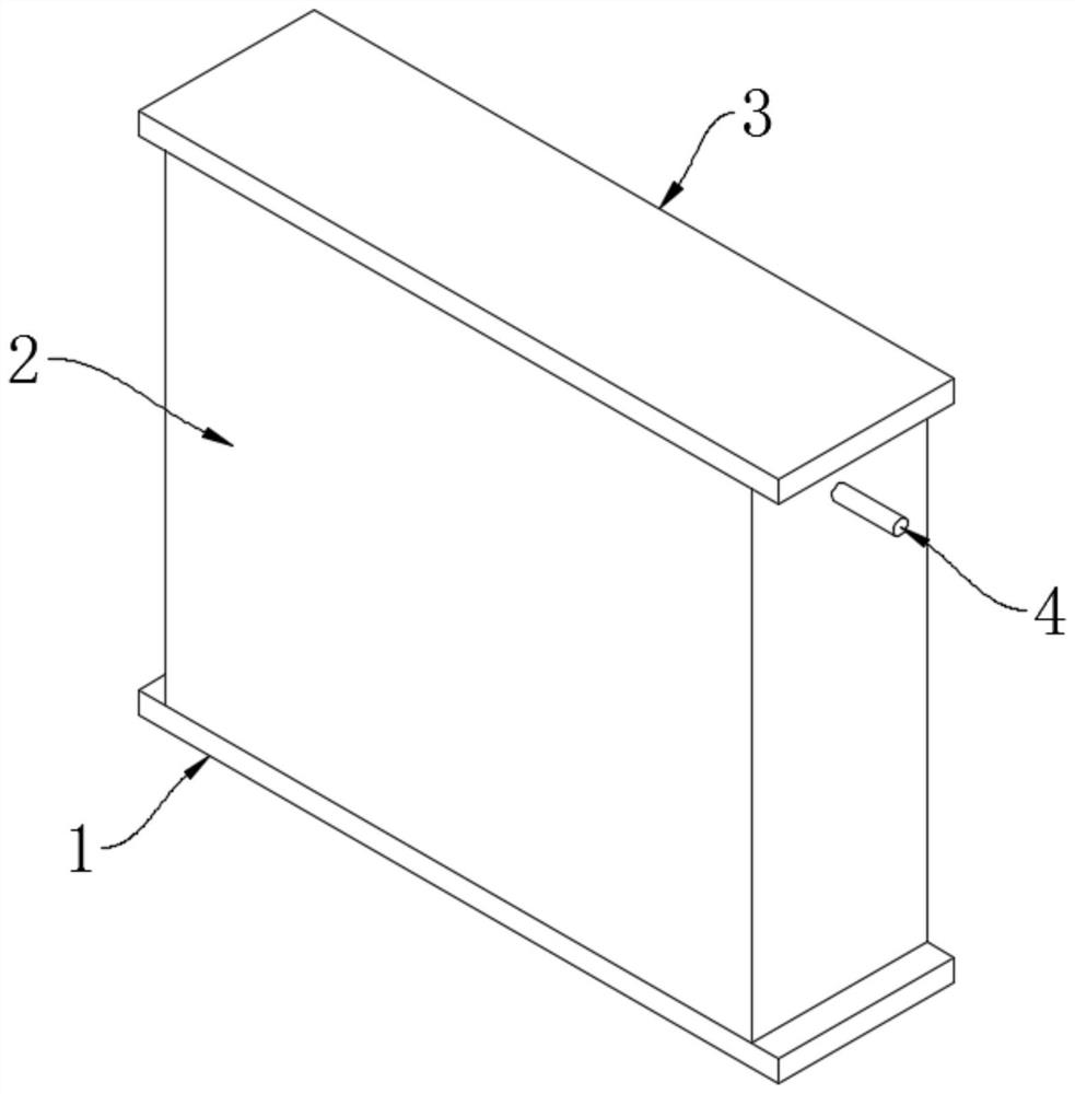
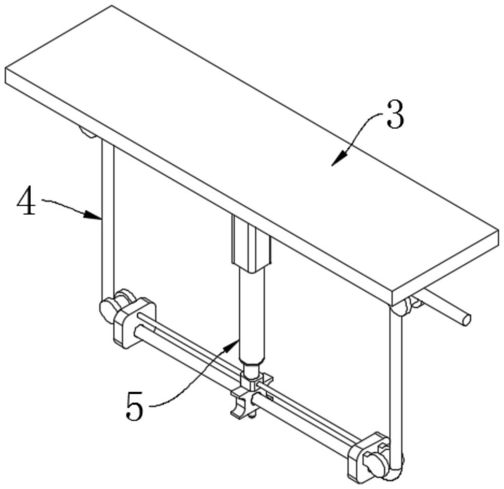
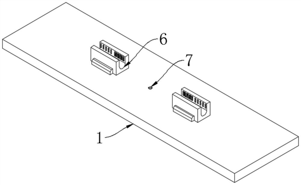
[0028] A DC charging cable for a charging vehicle, comprising a lower base 1, a lateral frame 2, an upper guard plate 3, a cable body 4, a lifting and rotating bidirectional cable winding assembly 5 and a cable surface cleaning mechanism 6, and the lateral frame 2 is welded on the bottom. Between the base 1 and the upper guard plate 3, a closed box is formed to effectively store the cable body 4 with excess length. The lifting and rotating bidirectional cable winding assembly 5 is fixedly installed at the bottom of the upper The cable body 4 is effectively stored, and can also be adjusted arbitrarily when the length of the cable body 4 needs to be adjusted, and the flexibility is higher. The cable surface cleaning mechanism 6 is fixedly installed on the top of the lower base 1, and the number of the cable surface cleaning mechanism 6 is two. The two cable surface cleaning mechanisms 6 are respectively located on both sides of the lifting and rotating two-way cable winding assem...

Embodiment 2

[0032] A DC charging cable for a charging vehicle, comprising a lower base 1, a lateral frame 2, an upper guard plate 3, a cable body 4, a lifting and rotating bidirectional cable winding assembly 5 and a cable surface cleaning mechanism 6, and the lateral frame 2 is welded on the bottom. Between the base 1 and the upper guard plate 3, the lifting and rotating bidirectional cable winding assembly 5 is fixedly installed at the bottom of the upper guard plate 3, the cable surface cleaning mechanism 6 is fixedly installed on the top of the lower base 1, and the number of the cable surface cleaning mechanism 6 For two, two cable surface cleaning mechanisms 6 are located on both sides of the lifting and rotating bidirectional cable winding assembly 5 respectively.

[0033] In this embodiment, on the basis of Embodiment 1, the internal layout of the lateral frame 2 is embodied, such as Figure 4 As shown, one side of the lifting and rotating bidirectional cable winding assembly 5 is f...

Embodiment 3

[0036] A DC charging cable for a charging vehicle, comprising a lower base 1, a lateral frame 2, an upper guard plate 3, a cable body 4, a lifting and rotating bidirectional cable winding assembly 5 and a cable surface cleaning mechanism 6, and the lateral frame 2 is welded on the bottom. Between the base 1 and the upper guard plate 3, the lifting and rotating bidirectional cable winding assembly 5 is fixedly installed at the bottom of the upper guard plate 3, the cable surface cleaning mechanism 6 is fixedly installed on the top of the lower base 1, and the number of the cable surface cleaning mechanism 6 For two, two cable surface cleaning mechanisms 6 are located on both sides of the lifting and rotating bidirectional cable winding assembly 5 respectively.

[0037] This embodiment embodies the structure of the lifting and rotating bidirectional cable winding assembly 5 on the basis of the above-mentioned embodiment, such as Figure 5 As shown, the lifting and rotating bidir...


PUM


Abstract

The invention discloses a direct-current charging cable for a charging automobile, and belongs to the technical field of automobile charging cables, the direct-current charging cable comprises a lower base, a lateral frame, an upper protection plate, a cable body, a lifting rotation type bidirectional cable winding assembly and a cable surface cleaning mechanism, the lateral frame is welded between the lower base and the upper protection plate; the lifting rotary type bidirectional cable winding assembly is fixedly installed at the bottom of the upper protection plate, the cable surface cleaning mechanisms are fixedly installed at the top of the lower base, the number of the cable surface cleaning mechanisms is two, and the two cable surface cleaning mechanisms are located on the two sides of the lifting rotary type bidirectional cable winding assembly correspondingly. According to the lifting rotary type bidirectional cable winding assembly, a cable body can be effectively stored, the length of the cable body can be adjusted at will when the length of the cable body needs to be adjusted, the flexibility is high, the cable surface cleaning mechanism can clean the surface of the cable body, it is guaranteed that the surface of the cable body is clean, and the service life of the cable body is prolonged. Therefore, stable use of the cable body is ensured.

Description

technical field [0001] The invention relates to a cable, in particular to a DC charging cable for charging vehicles, belonging to the technical field of vehicle charging cables. Background technique [0002] With the continuous development of society, the development and utilization of new energy has gradually entered the society, including electric vehicles. Electric vehicles refer to vehicles powered by on-board power supply and driven by motors that meet the requirements of road traffic and safety regulations. Vehicles, and in the use of charging vehicles, we need to use charging cables. The current DC charging cables for charging vehicles are basically simple connecting cables. Although the internal structure is relatively mature, the external structure is too simple. It is inconvenient to adjust the length of the cable, which is inconvenient for storage. A small number of cables with storage function have poor storage effect, certain damage to the inner core of the cabl...

Claims


Application Information

Patent Timeline
IPC IPC(8): B60L53/18B08B5/02B08B1/02
CPCB60L53/18B08B5/02B08B1/20
Inventor 安阳陈绍明谢忠邱资兴
Owner 广东坚宝电缆有限公司
Why Eureka
Try Eureka