
Hydraulic stepless speed change power wheel

A continuously variable speed, power wheel technology, used in transmissions, portable lifting devices, belts/chains/gears, etc., can solve problems such as inability to apply high-power vehicles, complex structures, and increased gear positions, to prevent oil circuit entanglement. , the effect of slowing down the negative impact and compressing the overall space

Pending Publication Date: 2020-04-10
QINGDAO AGRI UNIV
View PDF0 Cites 3 Cited by
  • Summary
  • Abstract
  • Description
  • Claims
  • Application Information

AI Technical Summary

Problems solved by technology

In the prior art, manual gearboxes and automatic gearboxes have complex structures, and most of them use gear combination shifting. In this shifting method, the more gears there are, the more parts will be in the gearbox. Generally, it is increased to 7 gears. In the end, the number of parts will exceed 500, which poses great challenges to technology and cost, and it is generally difficult to continue to increase the number of gears
In addition, the relatively mature steel belt continuously variable transmission technology uses steel belt for friction transmission, which is different from the transmission gear transmission. However, the steel belt continuously variable transmission technology is limited by the material properties and friction of the steel belt, so it cannot be applied in large power car

Method used


Image

  • Hydraulic stepless speed change power wheel
  • Hydraulic stepless speed change power wheel
  • Hydraulic stepless speed change power wheel

Examples


Embodiment Construction

[0023] In order to make the above objects, features and advantages of the present invention more comprehensible, specific implementations of the present invention will be described in detail below in conjunction with the accompanying drawings.

[0024] In the following description, specific details are set forth in order to provide a thorough understanding of the present invention. However, the present invention can be implemented in many other ways than those described here, and those skilled in the art can make similar extensions without departing from the connotation of the present invention. Accordingly, the present invention is not limited to the specific embodiments disclosed below.

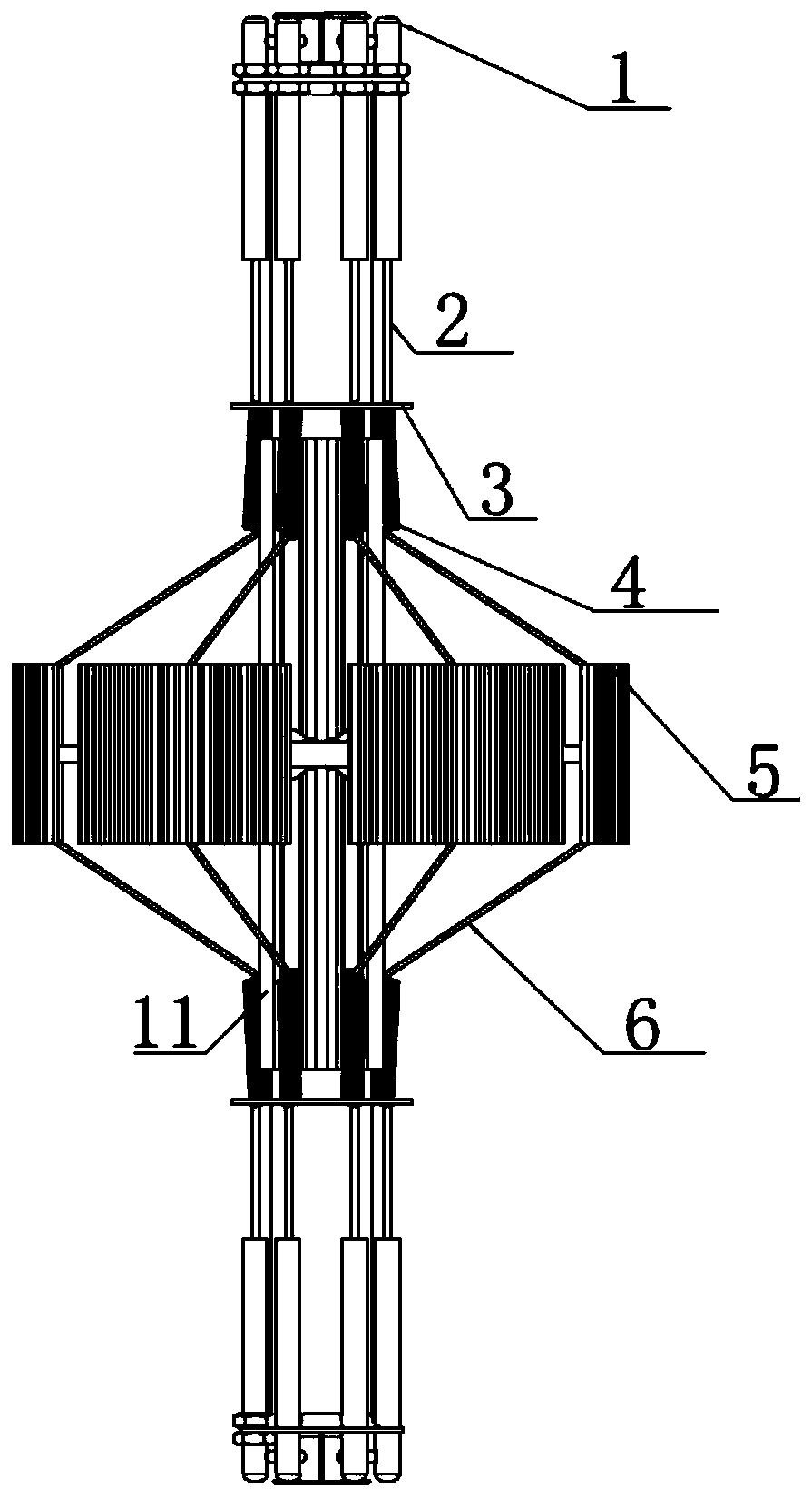
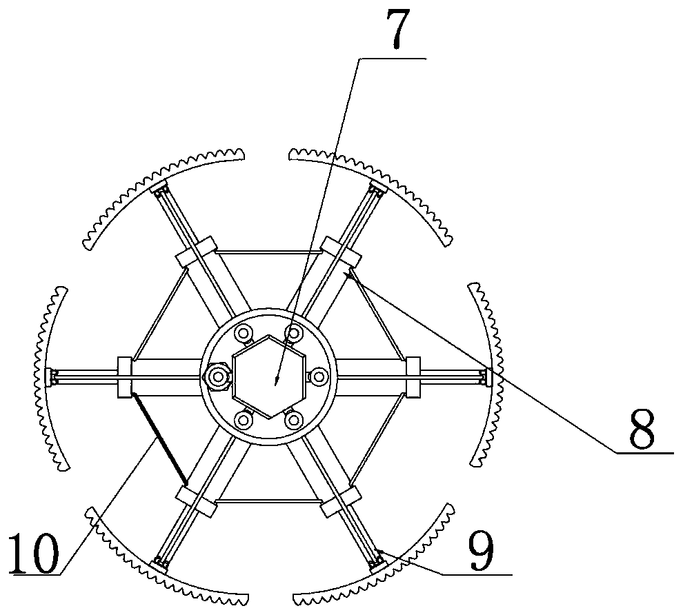
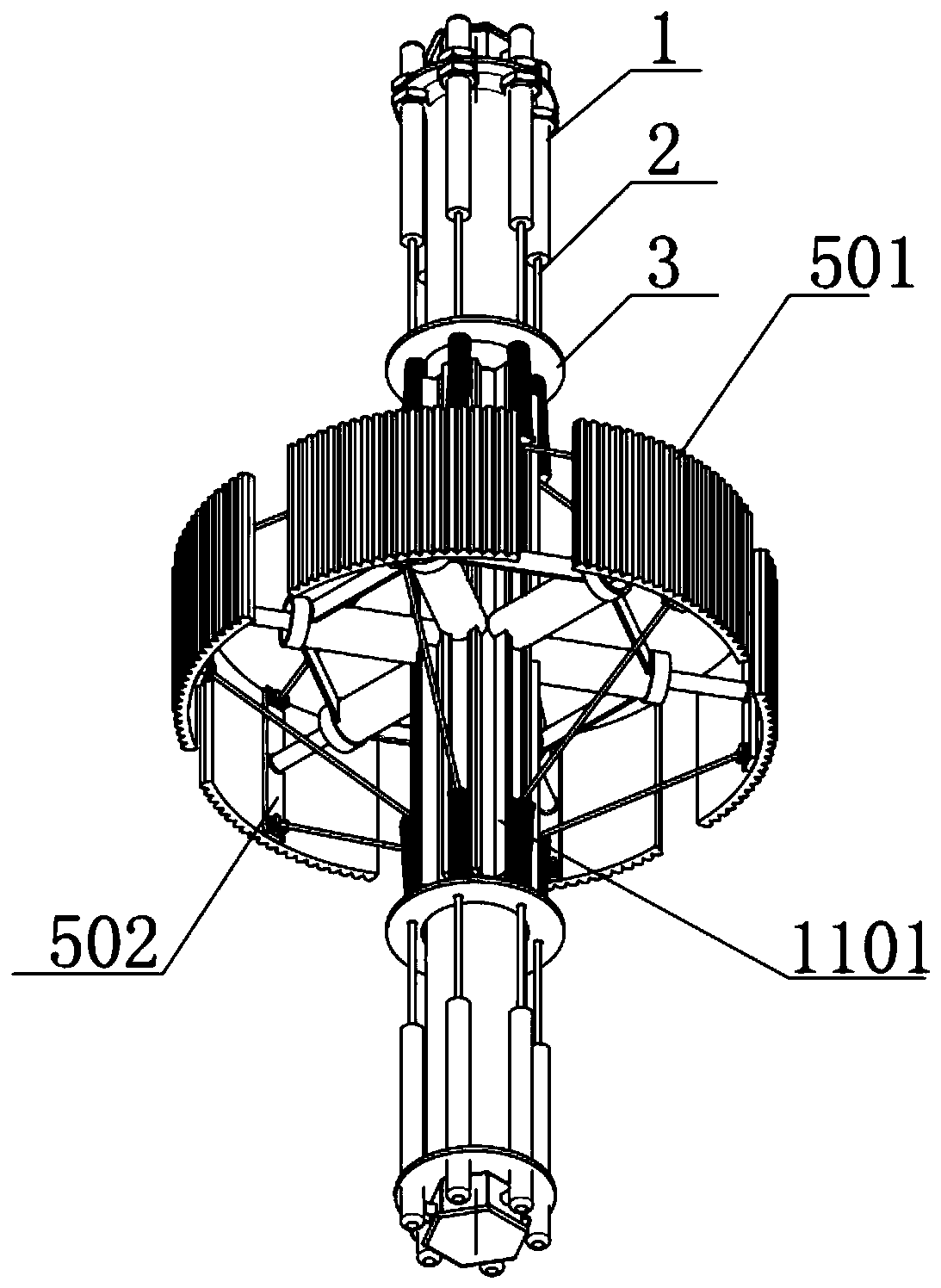
[0025] Figure 1 to Figure 3 The hydraulic continuously variable speed power wheel according to the present invention includes a slide bar 11 and active hydraulic pushing mechanisms respectively arranged at both ends of the slide bar 11. The slide bar 11 is provided with a driven hydraulic...


PUM


Abstract

The invention relates to an automobile driving wheel, in particular to a hydraulic stepless speed change power wheel. The hydraulic stepless speed change power wheel comprises a slide rod and drivinghydraulic pushing mechanisms arranged at the two ends of the sliding rod respectively; a driven hydraulic pushing mechanism is arranged on the sliding rod; and the sliding rod is connected with the outer contour of a hub through the driven hydraulic pushing mechanism. A plurality of sliding protrusions are arranged on the sliding rod in the circumferential direction of the sliding rod and arrangedin the axial direction of the sliding rod. The driven hydraulic pushing mechanism comprises central driven hydraulic housings and a central driven hydraulic push rod; the plurality of center driven hydraulic housings are arranged in the circumferential direction of the push rod at intervals; the center driven hydraulic housings are arranged in the radial direction of the push rod and connected with the push rod in a sliding mode; the adjacent center driven hydraulic housings are fixedly connected through connecting rods; and one ends of the center driven hydraulic push rods are arranged in the center driven hydraulic housings, and the other ends of the center driven hydraulic push rods are fixedly connected with the outer contour. The hydraulic stepless speed change power wheel is simplein structure, convenient to use, small in occupied space and not prone to being affected by external pressure.

Description

technical field [0001] The invention relates to an automobile drive wheel, in particular to a hydraulic continuously variable speed power wheel. Background technique [0002] In the development of automobiles, gearboxes, as the core part of automobiles, have been researched and improved all the time, among which the continuously variable transmission of automobiles is an important development direction. In the prior art, manual gearboxes and automatic gearboxes have complex structures, and most of them use gear combination shifting. When this shifting method has more shifting gears, there will be more parts in the gearbox. Generally, it is increased to 7 gears. In the end, the number of parts will exceed 500, which poses great challenges to technology and cost, and it is generally difficult to continue to increase the number of gears. In addition, the relatively mature steel belt continuously variable transmission technology uses steel belt for friction transmission, which ...

Claims


Application Information

Patent Timeline
Patent Type & Authority Applications(China)
IPC IPC(8): F16H55/54F16H9/10
CPCF16H55/54F16H9/10
Inventor 张鹏程王方艳
Owner QINGDAO AGRI UNIV
Learn More