Automatic pressure-stabilizing descaling water heater

A technology for automatic voltage stabilization and water heaters, which is applied in water heaters, fluid heaters, lighting and heating equipment, etc., and can solve the problems of scales easily attached to heating pipes

Active Publication Date: 2020-04-10
金迪(聊城市)知识产权运营有限公司
View PDF8 Cites 4 Cited by
  • Summary
  • Abstract
  • Description
  • Claims
  • Application Information

AI Technical Summary

Problems solved by technology

[0005] The purpose of the present invention is to solve the problem that scale is easily attached to the heating tubes of most tradi

Method used


Image

  • Automatic pressure-stabilizing descaling water heater
  • Automatic pressure-stabilizing descaling water heater
  • Automatic pressure-stabilizing descaling water heater

Examples


Embodiment 1

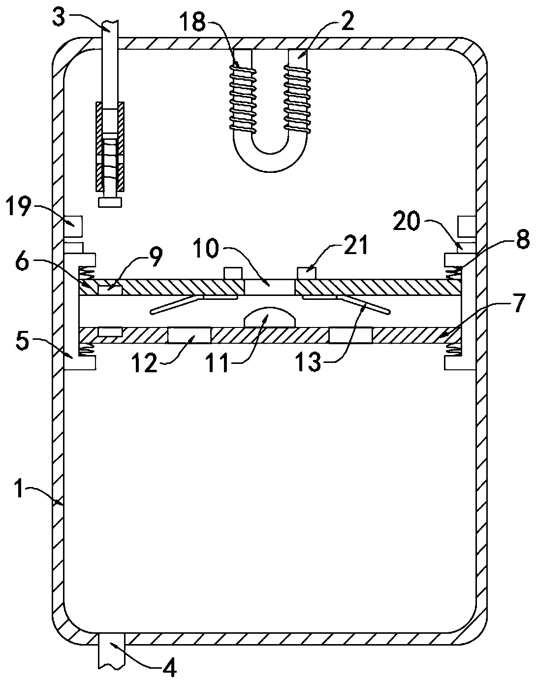
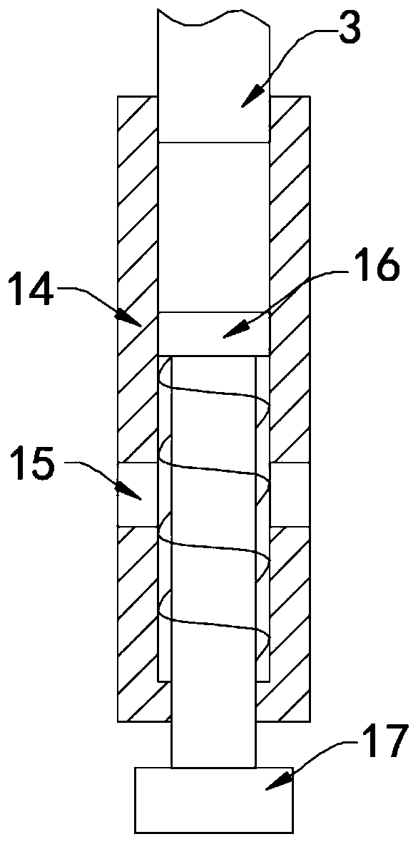
[0023] Such as Figure 1-3 As shown, a water heater with automatic voltage stabilization and descaling includes a water tank 1, a heating pipe 2, a water inlet pipe 3 and a water outlet pipe 4, the heating pipe 2 is arranged on the inner top surface of the water tank 1, and the water inlet pipe 3 and the water outlet pipe 4 are respectively fixed Connected to the upper end and the lower end of the water tank 1, a controller (not shown in the figure) is provided in the water inlet pipe 3, which can control the intermittent flow of water into the water tank 1 through the water inlet pipe 3, and the water tank 1 is provided with two cross sections. U-shaped sliding block 5, two sliding blocks 5 are arranged symmetrically with respect to the heat receiving pipe 1 and are sealed and slidably connected with the side wall of the water tank 1.

[0024] An upper plate 6 and a lower plate 7 are arranged between the two sliding blocks 5, and the opposite sides of the upper plate 6 and th...

Embodiment 2

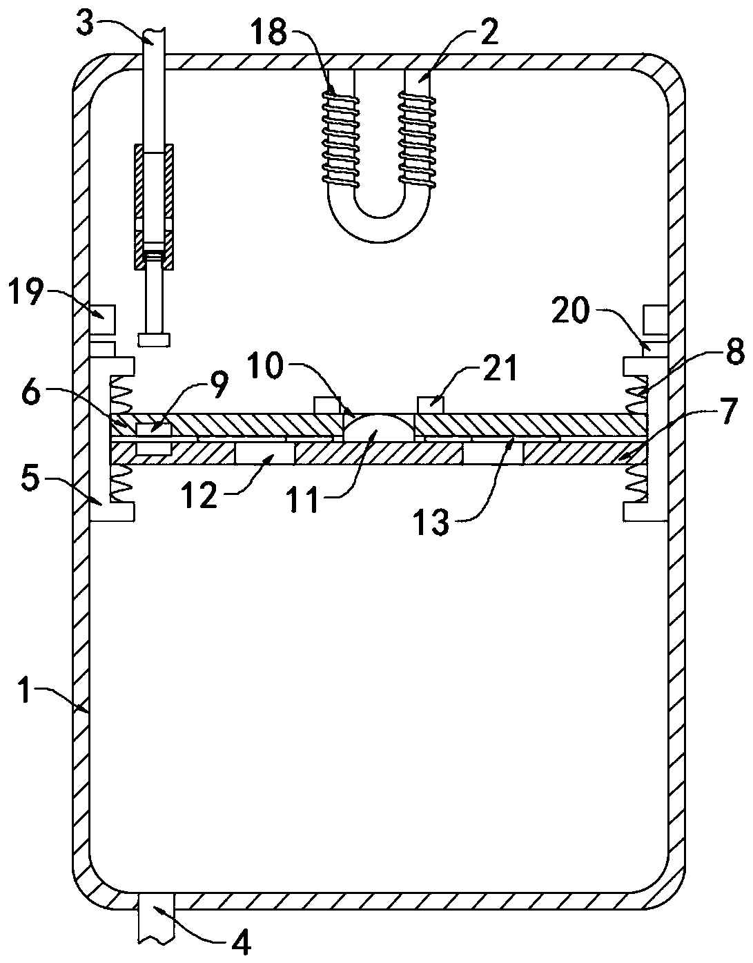
[0036] Such as Figure 4-5 As shown, the difference between this embodiment and Embodiment 1 is that the upper side wall of the upper plate 6 is rotatably connected with an annular pipe 22 through a connecting rod, and the annular pipe 22 is provided with a stirring fan 25 that can rotate around its center to stir The blades of the fan 25 are externally connected to the annular pipe 22. The annular pipe 22 is tightly filled with a plurality of thermal expansion balls 23. The thermal expansion balls 23 are composed of an elastic bag and an expansion medium filled inside. The expansion medium can be changed with temperature. The kerosene that changes significantly, kerosene can absorb higher temperature and make the thermal expansion ball 23 expand, when the temperature is lower than the expansion temperature of kerosene, the thermal expansion ball 23 will gradually return to its original state, each thermal expansion ball 23 is equipped with Counterweight 24.

[0037] In this ...


PUM


Abstract

The invention belongs to the field of household appliances, and especially relates to an automatic pressure-stabilizing descaling water heater. The water heater comprises a water tank, a heating pipe,a heating pipe and a water outlet pipe. The heating pipe is arranged at the inner top surface of the water tank, the water inlet pipe and the water outlet pipe fixedly communicate with the upper endand the lower end of the water tank, two sliding blocks with U-shaped sections are arranged in the water tank, the two sliding blocks are symmetrically arranged relative to a heat receiving pipe and are in sealed sliding connection with the side wall of the water tank, an upper plate and a lower plate are arranged between the two sliding blocks, the opposite faces of the upper plate and the lowerplate are connected with the inner side walls of the sliding blocks through extension springs and are in sealed sliding connection with the side walls of the sliding blocks, permanent magnets with thesame polarity attracting each other are fixedly embedded in the opposite side walls of the upper plate and the lower plate, a plurality of upper through holes are formed in the upper plate, a plurality of stand columns matched with the upper through holes are arranged on the lower plate, and a plurality of lower through holes are formed in the lower plate. By arranging the descaling mechanism, scale on the heating pipe is scraped off along with up-down movement of an induction coil on the heating pipe, and cleanliness of the heating pipe can be effectively guaranteed.

Description

technical field [0001] The invention belongs to the field of home appliances, in particular to an automatic voltage-stabilizing and descaling water heater. Background technique [0002] Water heaters can be divided into electric water heaters, gas water heaters and solar water heaters according to different principles. They are devices that heat the water in the water tank according to different principles, thereby supplying hot water for daily life, which can greatly facilitate people's lives, so use extremely broad. [0003] During the use of most traditional water heaters, with the reduction of hot water in the water tank, the pressure of the water outlet at the bottom of the water tank will decrease with the drop of the liquid level of the water tank, which will lead to insufficient pressure at the water outlet and a small water outlet rate. , affecting the use, and when the water level in the water tank drops to a certain position, the water inlet pipe will automatical...

Claims


Application Information

Patent Timeline
IPC IPC(8): F24H1/18F24H9/00F24H9/18F24H9/20
CPCF24H1/181F24H1/185F24H9/0005F24H9/0042F24H9/1818F24H9/2021
Inventor 林小帅柴明坤
Owner 金迪(聊城市)知识产权运营有限公司
Why Eureka
Try Eureka