Sound pressure sensor

A sound pressure sensor and sensing layer technology, applied in instruments, measuring ultrasonic/sonic/infrasonic waves, measuring devices, etc., can solve the problem of insufficient sensitivity of the sound pressure sensor, achieve moderate overall stiffness, improve sensitivity, and ensure sensitivity. Effect

Active Publication Date: 2020-04-10
BOE TECH GRP CO LTD
View PDF12 Cites 2 Cited by
  • Summary
  • Abstract
  • Description
  • Claims
  • Application Information

AI Technical Summary

Problems solved by technology

[0005] The main purpose of the present invention is to provide a sound pressure sensor so that it can solve the technical problem of insufficient sensitivity of the sound pressure sensor in the prior art

Method used


Image

  • Sound pressure sensor
  • Sound pressure sensor
  • Sound pressure sensor

Examples


Embodiment 1

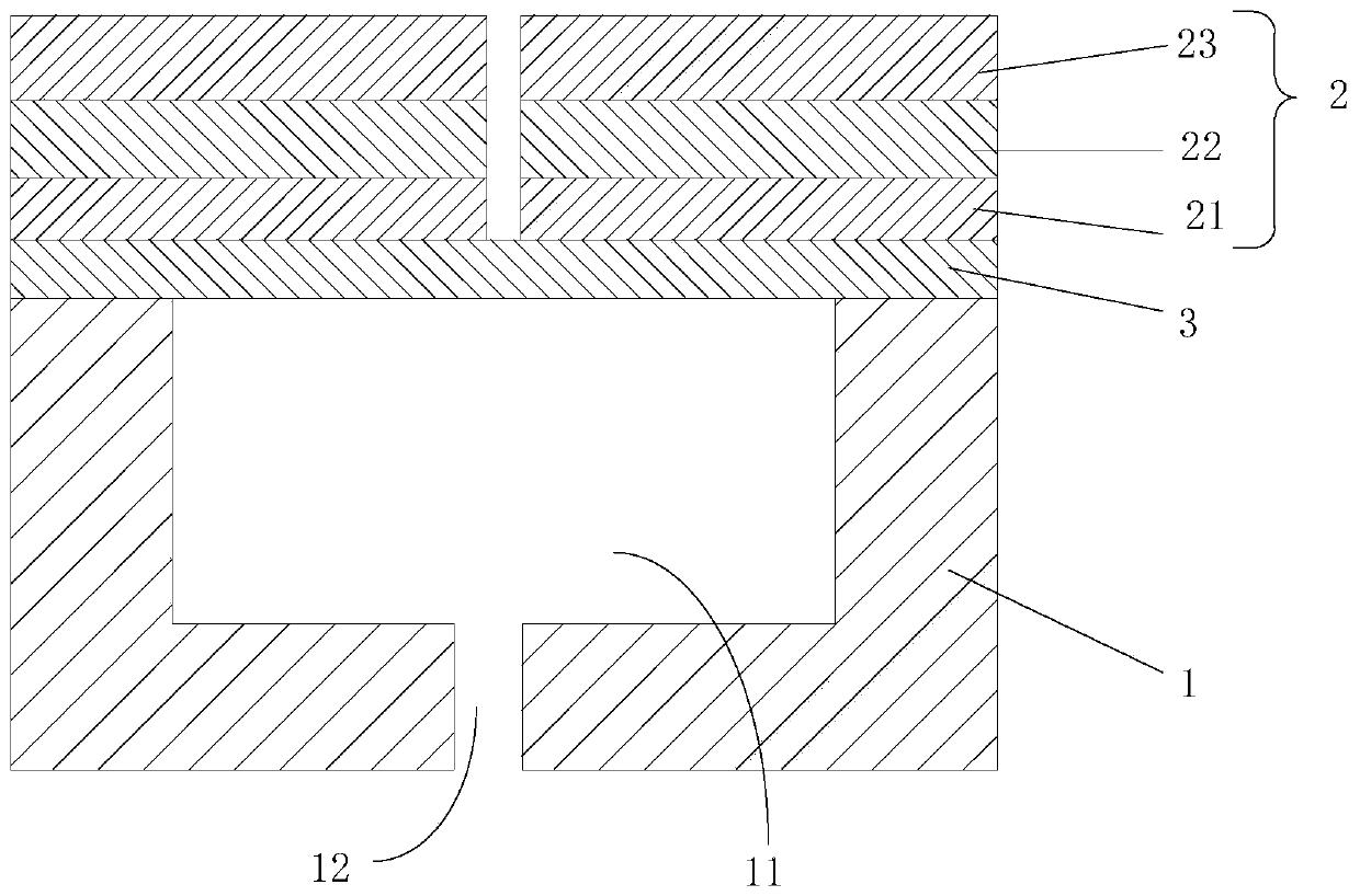
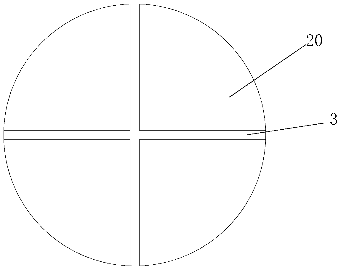
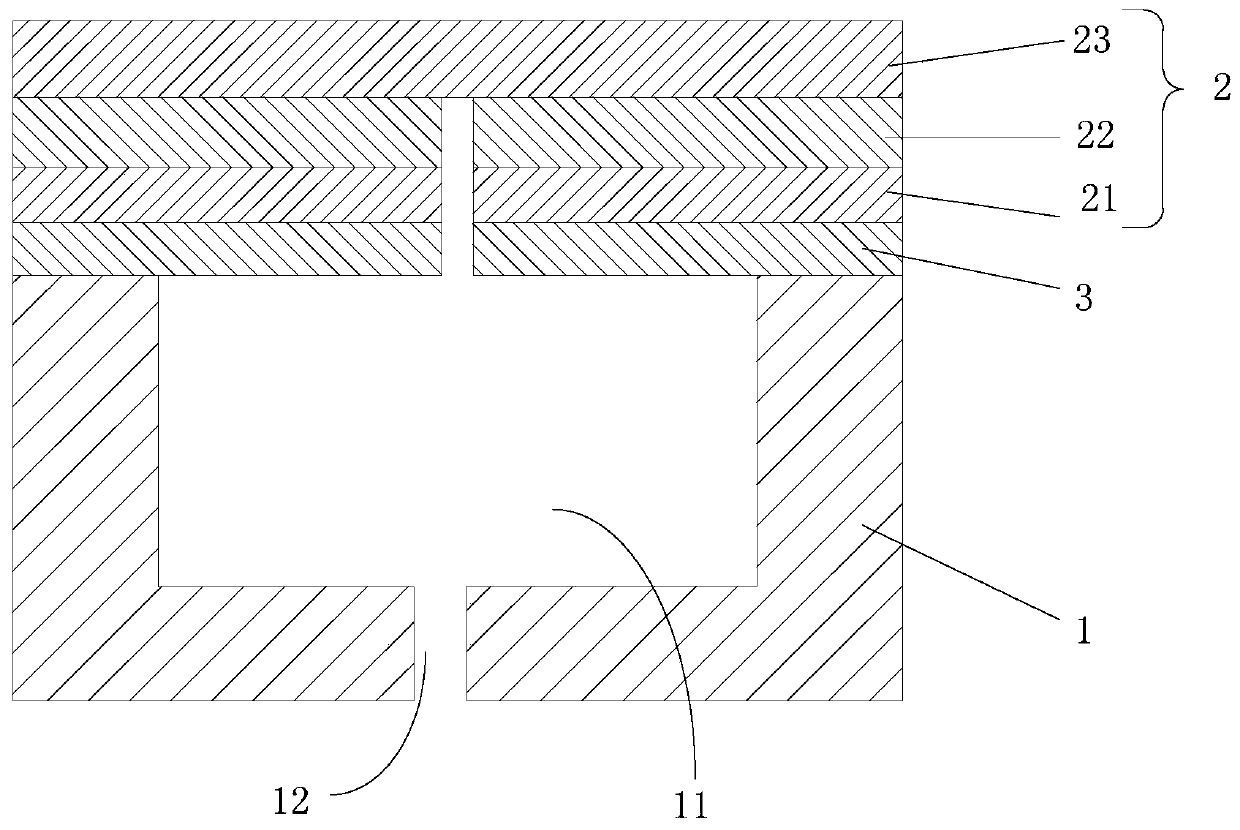
[0033] Such as Figure 1-Figure 4 As shown, the first embodiment of the present invention proposes a sound pressure sensor, which includes: a substrate 1, a sensing layer 2 and an elastic layer 3; the first end of the substrate 1 is provided with a recessed space toward the opposite second end 11. The sensing layer 2 is laminated with the elastic layer 3, and covers the first end of the substrate 1 and is connected to the substrate 1; wherein, the sensing layer 2 takes the center point as the initial division point , evenly divided into more than or equal to 2 sub-sensing layers 20, there is a preset distance between two adjacent sub-sensing layers 20, and the sensing layer 2 can drive the elastic layer 3 to the The deformation in the concave space 11 of the substrate 1 converts the acoustic wave signal into an electrical signal.

[0034] Specifically, the substrate 1 can be rigid, for example, the substrate 1 can be a glass substrate, or the substrate 1 can be elastic, for e...


PUM


Abstract

The invention relates to a sound pressure sensor, and relates to the technical field of acoustoelectric sensing. According to the main technical scheme, the sound pressure sensor comprises a substrate, an induction layer and an elastic layer, wherein the first end of the substrate is provided with a concave space towards the opposite second end; the induction layer and the elastic layer are arranged in a stacked mode, and the induction layer covers the first end of the substrate and is connected with the substrate; the induction layer is uniformly divided into two or more sub-induction layersby taking a central point as a starting division point, and a preset distance is formed between every two adjacent sub-induction layers; and the induction layer can drive the elastic layer to deform towards the concave space of the substrate when being subjected to the pressure of sound waves and convert acoustic wave signals into electric signals. The sound pressure sensor solves the problem thata sound pressure sensor in the prior art is insufficient in sensitivity.

Description

technical field [0001] The invention relates to the technical field of acoustic-electric sensing, in particular to an acoustic pressure sensor. Background technique [0002] The sound pressure sensor is a device that can detect sound waves and convert the sound waves into electrical signals for output. [0003] In the prior art, the sound sensing element of the sound pressure sensor is a diaphragm that can vibrate under the pressure of the sound wave, that is, the vibrating diaphragm bends and vibrates under the pressure of the sound wave and uses the principle of the piezoelectric effect to convert the sound wave signal into an electrical signal output . Among them, in order to make the vibrating diaphragm have sensitive sensing performance, the vibrating diaphragm is divided into multiple cantilever-shaped diaphragms. At this time, the gap after division must not be too large, because the acoustic resistance will decrease if the gap is too large , the frequency response ...

Claims


Application Information

Patent Timeline
Patent Type & Authority Applications(China)
IPC IPC(8): G01H11/08
CPCG01H11/08
Inventor 刘英明王海生李佩笑韩艳玲张晨阳郭玉珍赵利军李秀锋姬雅倩
Owner BOE TECH GRP CO LTD
Why Eureka
Try Eureka