Cable intermediate connector

A cable intermediate joint and cable connection technology, applied in the direction of cable joints, etc., can solve the problems of troublesome installation and operation, wear and loosening, bursting, etc., and achieve the effect of convenient installation, convenient installation and simple structure

Active Publication Date: 2021-06-01
埃塞克斯电气(南京)有限公司
View PDF8 Cites 2 Cited by
  • Summary
  • Abstract
  • Description
  • Claims
  • Application Information

AI Technical Summary

Problems solved by technology

[0002] At present, the cable connection operation is the main operation item in the electric power construction. It is mainly due to the influence of the manufacturing process and transportation capacity, the length of the cable preparation is limited, and it needs to be connected. The cable connection position needs to be connected with the cable intermediate joint. , the strength, sealing, explosion-proof and flame retardancy of the whole cable are the worst at the joint position, and often due to arc flash and other faults, the middle joint position of the cable will catch fire or burst, affecting power transmission, affecting adjacent circuits, and causing the overall power system to be paralyzed. For the power supply line of the equipment, the loss of equipment downtime caused by sudden power failure is more serious, so fire prevention measures should be taken for the above-mentioned power intermediate joints
[0003] The existing fire protection measures include adding copper sleeves, nuts or ceramic lamp elements to the cable intermediate joints for fire prevention, which leads to a complex overall structure of the connecting joints, troublesome installation and operation, and cannot adapt to different cable intermediate joints
[0004] There are also rubber protective layers for fire protection, mainly using the sealing properties of rubber for fire protection, but the fit rate of rubber and cables is low, and it cannot form the effect of fire protection for different cables, and the rubber is directly in contact with the nodes, which is easy to appear. wear loose phenomenon
[0005] Publication number CN201298725 discloses a fireproof and explosion-proof device for cable intermediate joints. The casing, the fire-proof section is composed of a fire-proof cavity between the damping baffle and the port near the two-end ports of the explosion-proof casing, and the fire-proof cavity is filled with fire-proof blocking material. The device adopts a hollow structure. And filling the protective material, the overall operation process is complicated, the operation steps are increased, the overall operation efficiency is low, and the inner wall is in direct contact with the cable
[0006] Publication number CN208874257U discloses a stackable cable intermediate joint protective shell, including a base, an upper cover and a stacking base; wherein: the base and the upper cover are semi-enclosed structures, and the base and the upper cover The openings are arranged opposite to each other, and the accommodating space formed by the base and the upper cover is used for placing two side-by-side middle joints of high-voltage cables; the base is respectively formed with a first docking rod and a second docking rod at both ends, and its direction It is perpendicular to the long side of the cable intermediate joint protective shell; a docking shaft and a docking hole are respectively formed at the two ends of the first docking rod and the second docking rod; Cooperate with the docking holes; the stacking base is formed with a docking shaft for matching with the docking holes on the first docking rod and the second docking rod. The structure of the device is complicated. Set up the package structure, and the above problems will still exist if the original joint method is used

Method used


Image

  • Cable intermediate connector
  • Cable intermediate connector
  • Cable intermediate connector

Examples


Embodiment Construction

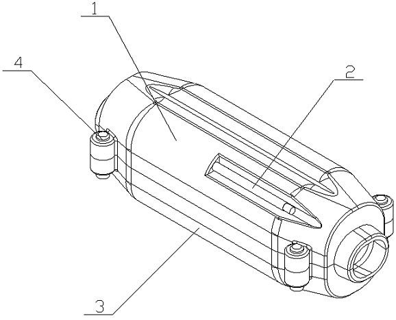
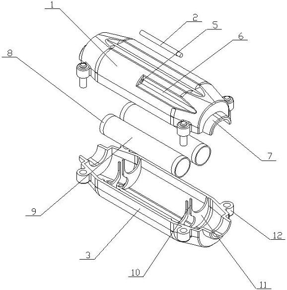
[0032] The cable intermediate joint of the present invention is realized in this way: the cable intermediate joint of the present invention includes an upper fixed connection part, a lower fixed connection part and a rubber sleeve (9) for negative pressure expansion, and the upper fixed connection part and the lower fixed connection part are fastened by fastening screws (4) Connect, and form a closed cavity to accommodate the cable connection point, the rubber sleeve (9) is placed on the cable connection point, and the two ends are tightly wrapped with the cables on both sides of the cable connection point, the upper fixed connection part An air suction channel is provided, and negative pressure is generated in the air suction airtight cavity to expand the rubber sleeve (9).

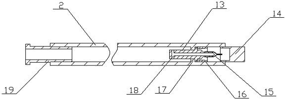
[0033] The upper fixed connection part is composed of the upper shell (1), the air pipe (2), the communication hole (5), the pipeline groove (6), the end pressure plate (7), the guide rod (10), the suppor...


PUM


Abstract

The cable intermediate joint of the invention discloses a cable intermediate joint in which an air cavity sealing area is arranged at the cable connection position to protect and isolate the cable connection. The structure is simple, the use is convenient and fast, and the safety is better. It is characterized in that it includes an upper fixed connection part, a lower fixed connection part and a rubber sleeve for negative pressure expansion. The upper fixed connection part and the lower fixed connection part are connected by fastening screws, and form The airtight cavity accommodates the cable connection point, the rubber sleeve is placed at the cable connection point, and the two ends are tightly wrapped with the cables on both sides of the cable connection point. Negative pressure is generated inside to expand the rubber sleeve.

Description

technical field [0001] The invention relates to a cable intermediate joint, which relates to an intermediate joint which protects the connection position from fire when cables are connected, and belongs to the field of cable communication. In particular, it relates to a cable intermediate connector which is provided with an air chamber sealing area at the cable connection position to protect and isolate the cable connection. Background technique [0002] At present, the cable connection operation is the main operation item in the electric power construction. It is mainly due to the influence of the manufacturing process and transportation capacity, the length of the cable preparation is limited, and it needs to be connected. The cable connection position needs to be connected with the cable intermediate joint. , the strength, sealing, explosion-proof and flame retardancy of the whole cable are the worst at the joint position, and often due to arc flash and other faults, the ...

Claims


Application Information

Patent Timeline
Patent Type & Authority Patents(China)
IPC IPC(8): H02G15/18
CPCH02G15/18
Inventor 王红州
Owner 埃塞克斯电气(南京)有限公司
Why Eureka
Try Eureka