Backlight adjusting method and backlight adjusting device

A backlight adjustment and backlight technology, which is applied in the automotive field, can solve the problems of excessively bright backlight, limited adjustment range, and unfavorable drivers from viewing information on the instrument, and achieves the effect of facilitating driving conditions and expanding the range.

Active Publication Date: 2020-04-10
大陆汽车车身电子系统(芜湖)有限公司
View PDF7 Cites 0 Cited by
  • Summary
  • Abstract
  • Description
  • Claims
  • Application Information

AI Technical Summary

Problems solved by technology

[0005] Even if the ambient light changes, such as entering and exiting tunnels and tree shades, or the sun entering and exiting clouds, etc., if you do not manually adjust the backlight adjustment knob or switch the small light switch, the backlight will not change accordingly to adapt to the change in ambient light. It is beneficial for the driver to view the information on the instrument. If manual adjustment is performed at this time, it will affect driving safety
[0006] In addition, the range that can be adjusted is limited. For example, when the vehicle is driving on a road with strong sunlight, when entering the tunnel entrance, even if it is adjusted to the minimum duty cycle, the corresponding backlight is still too bright. The empty ratio, the corresponding backlight is still insufficient, the backlight of the instrument display is insufficient or the backlight is too bright, the instrument cannot be displayed at a suitable brightness, which will affect the driver's accurate grasp of the driving situation

Method used


Image

  • Backlight adjusting method and backlight adjusting device
  • Backlight adjusting method and backlight adjusting device

Examples


Embodiment Construction

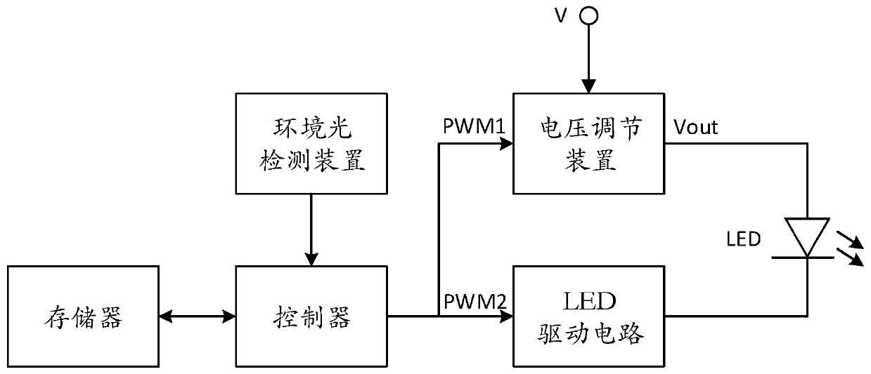
[0038] Such as figure 1 As shown, the backlight adjustment device of an embodiment of the present invention includes a controller, an ambient light detection device, a voltage adjustment device, and an LED drive circuit. The output first adjusting signal adjusts the output voltage Vout, the output terminal of the LED driving circuit is connected to the negative pole of the backlight LED, and the LED driving circuit controls the turn-on time of the backlight LED according to the second adjusting signal output by the controller.

[0039] The ambient light detection device can be realized by a photosensitive device, such as a photoresistor, a photodiode or other photosensitive sensors.

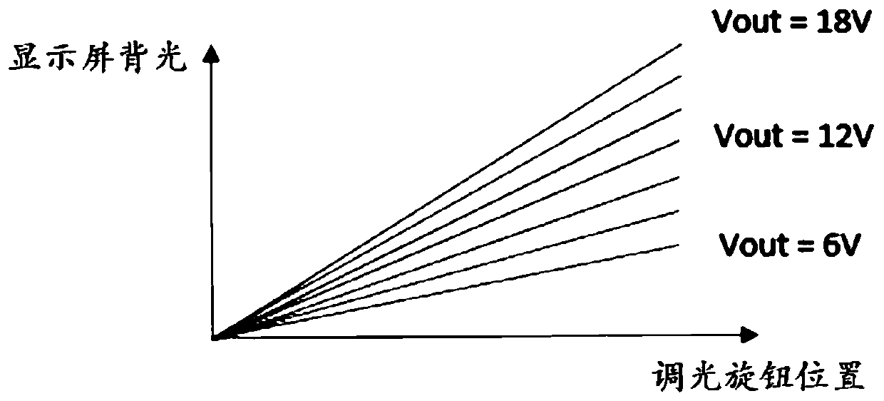
[0040] The voltage regulating device may be an adjustable voltage regulator capable of outputting a voltage lower than the power supply voltage V and / or higher than the power supply voltage V. In this embodiment, the power supply voltage V is, for example, 12V, and the output voltage Vout of the...


PUM


Abstract

The invention provides a backlight adjusting method. The backlight adjusting device comprises a controller, an ambient light detection device, a voltage adjusting device and an LED driving circuit. The voltage adjusting device adjusts an output voltage according to a first adjusting signal, the LED driving circuit controls the turn-on time of the backlight LED according to a second adjusting signal, and the method comprises the following steps: obtaining first ambient light from the ambient light detection device; determining the first adjusting signal according to the first ambient light; determining a second adjusting signal according to the position of a dimming knob; and outputting the first adjusting signal to the voltage adjusting device, and outputting the second adjusting signal tothe LED driving circuit. The invention further provides a backlight adjusting device. According to the backlight adjusting method and the backlight adjusting device provided by the invention, the switching-on time of the backlight LED is adjusted, and the power supply voltage of the backlight LED is also adjusted, so that the backlight brightness adjusting range of a display screen can be expanded, the backlight adjusting method and the backlight adjusting device are suitable for various driving conditions of a vehicle, and a driver can accurately master the driving conditions conveniently.

Description

technical field [0001] The invention relates to the field of automobiles, in particular to a backlight adjustment method and a backlight adjustment device. Background technique [0002] Currently, the backlighting of instrument displays is provided by LEDs. [0003] In the traditional backlight adjustment scheme, the backlight adjustment of the display screen is realized by controlling the length of the conduction time of the LED (that is, the average current flowing through the LED) and by adjusting the duty cycle of the PWM (pulse width modulation) signal. [0004] There are usually two modes of day and night, and the two modes are switched by a small light switch, which is completely a manual control mode. [0005] Even if the ambient light changes, such as entering and exiting tunnels and tree shades, or the sun entering and exiting clouds, etc., if you do not manually adjust the backlight adjustment knob or switch the small light switch, the backlight will not change a...

Claims


Application Information

Patent Timeline
Patent Type & Authority Applications(China)
IPC IPC(8): H05B45/12
CPCY02B20/40
Inventor 常喜许劲郑东刘如根
Owner 大陆汽车车身电子系统(芜湖)有限公司
Why Eureka
Try Eureka