
Display panel and display apparatus

A technology for display panels and substrates, applied in nonlinear optics, instruments, optics, etc., can solve the problems of increasing the amount of modulated light, uneven brightness, and easily fluctuating threshold voltage, achieving high dynamic range, preventing transmittance, and wide color. Domain and Dynamic Range Effects

Inactive Publication Date: 2020-04-10
SAKAI DISPLAY PROD
View PDF16 Cites 0 Cited by
  • Summary
  • Abstract
  • Description
  • Claims
  • Application Information

AI Technical Summary

Problems solved by technology

[0012] However, the area active method has the problem that the boundaries between the areas of the divided backlight unit are visible, so it is not preferable to increase the ratio of the modulated light amount.
In addition, the principle of the IPS method is that the threshold voltage tends to fluctuate due to variations in the width of the comb-shaped electrodes and the distance between the electrodes, so brightness unevenness tends to occur.

Method used


Image

  • Display panel and display apparatus
  • Display panel and display apparatus
  • Display panel and display apparatus

Examples


Embodiment Construction

[0067] Below, use Figure 1 to Figure 11 One embodiment of the present invention will be described.

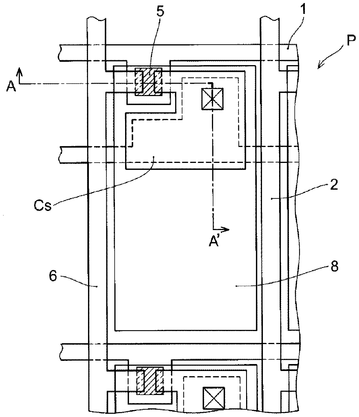
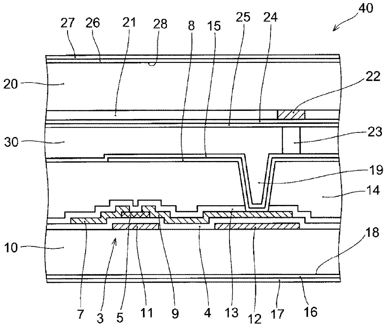
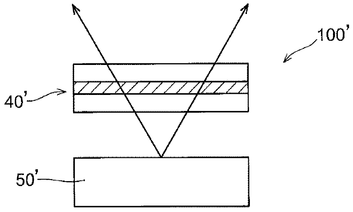
[0068] First, the structure of a unit pixel of a display device 100 according to an embodiment of the present invention will be described based on FIG. 1 . The display device 100 of this embodiment includes: a first substrate 10 on which TFTs and pixel electrodes are formed, a second substrate 20 on which a counter electrode is formed, and a liquid crystal having The display panel 40 of the layer 30 further includes a light source unit 50 that emits light toward the first substrate 10 , and a light diffusion member 60 that diffuses and outputs the light emitted from the display panel 40 .

[0069] Figure 1A is the front view of the region of the unit pixel P viewed from the front, Figure 1B is along Figure 1A A cross-sectional view of the unit pixel P viewed from the side along the A-A' line. Such as Figure 1B As shown, the unit pixel is divided by adjacent two of the ...


PUM


Abstract

The present invention pertains to: a display panel provided with a first substrate, a second substrate, a liquid crystal layer that is held between the substrates, a first orientation film that is provided to a surface facing the liquid crystal layer of the first substrate, and a second orientation film that is provided to a surface facing the liquid crystal layer of the second substrate; and a display apparatus provided with the display panel. This display panel is configured such that all directors of a plurality of liquid crystal compositions constituting the liquid crystal layer are substantially perpendicular to the first orientation film and the second orientation film when no voltage is applied, a liquid crystal layer included in each of a plurality of unit pixels arranged in a matrix along row and column directions has a single orientation state, the director of the liquid crystal composition positioned at the center of a first unit pixel which is one of the unit pixels is reverse to the director of the liquid crystal composition positioned at the center of a second unit pixel which is present in the same row or column as that of the first unit pixel.

Description

technical field [0001] The invention relates to a display panel and a display device. Background technique [0002] Liquid crystal display devices are widely used not only in small and medium-sized display devices such as portable electronic devices, but also in display devices used in televisions, digital signage, and the like. The penetration rate of large display devices is increasing year by year, and in particular, the proportion of display devices having a size of 50 inches or more is increasing. However, considering the ease of installation, it is not preferable to blindly increase the size of the display device, and it is considered that the size of the display device for at least personal use is about 75 inches at most. [0003] On the other hand, the demand for high-definition display devices is still high, so the number of pixels of the display devices is still increasing. Specifically, from the previous full high-definition FHD (1,920×1,080, 8,294,400 dots) to ...

Claims


Application Information

Patent Timeline
Patent Type & Authority Applications(China)
IPC IPC(8): G02F1/1337G02F1/1335G02F1/13357G02F1/1368
CPCG02F1/133757G02F1/133742G02F1/1337G02F1/136209G02F1/1368
Inventor 前田温子山田晋太郎近藤克己中川英树山下俊弘
Owner SAKAI DISPLAY PROD
Learn More