
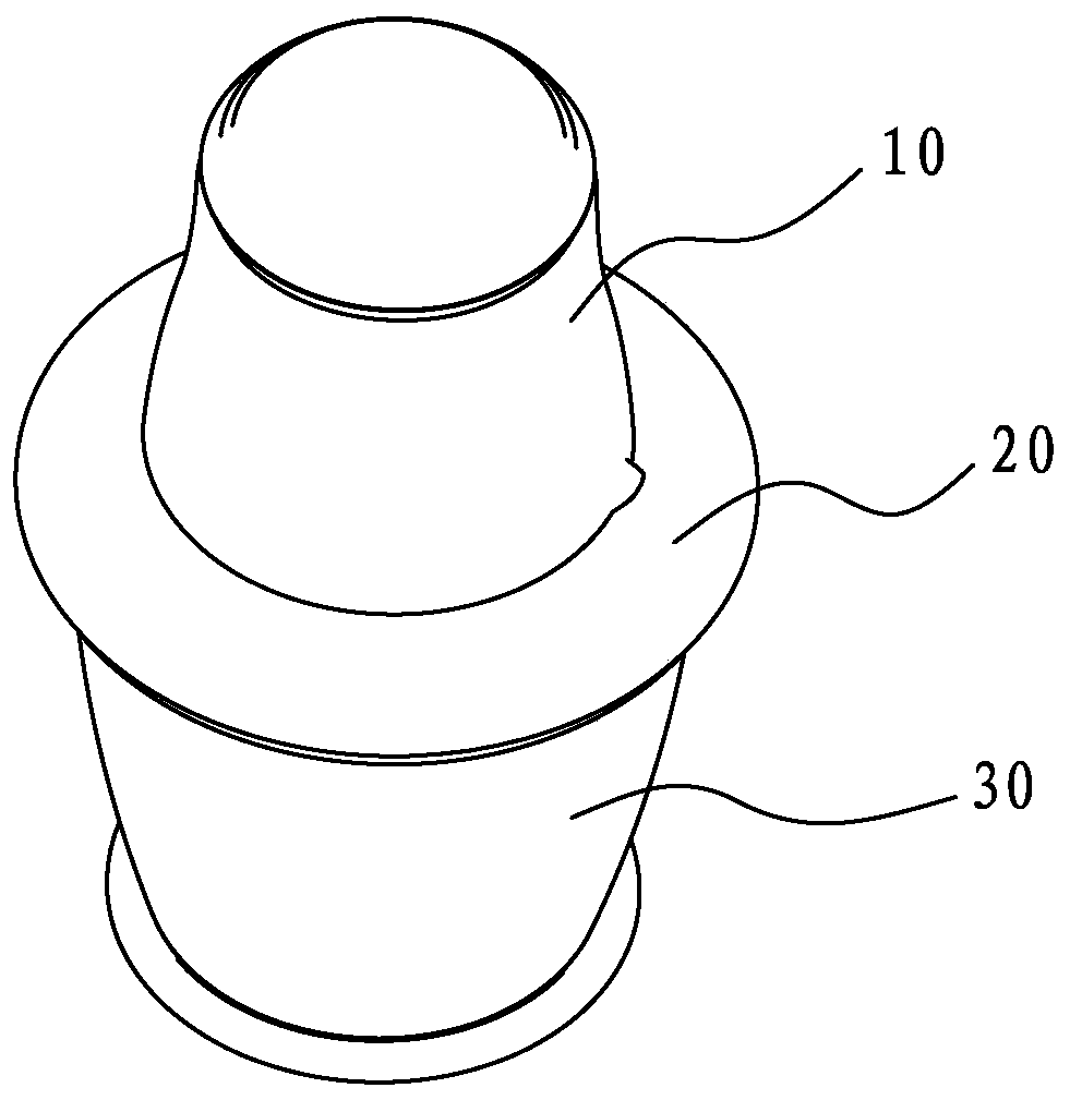
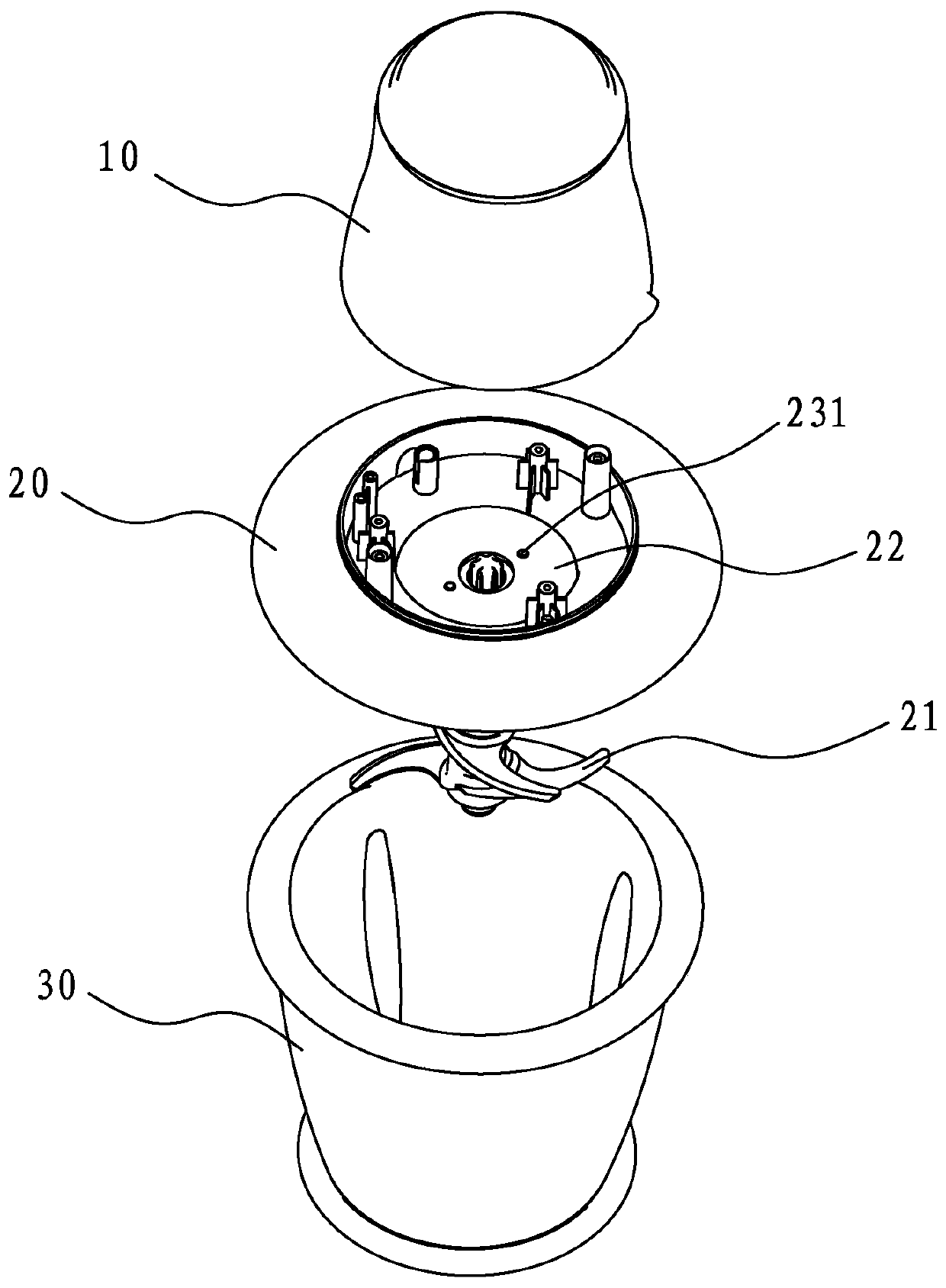
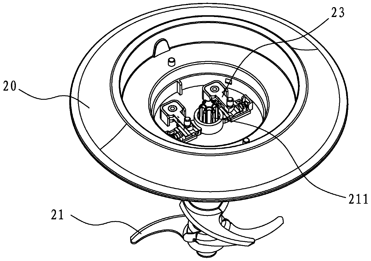
Chopping knife brake structure and chopping machine

A shredding knife and shredder technology, which can be used in household appliances, applications, kitchen utensils, etc., and can solve problems such as safety hazards

Pending Publication Date: 2020-04-14
JIANGMEN KINGFAI ELECTRICAL APPLIANCE IND
View PDF0 Cites 1 Cited by
  • Summary
  • Abstract
  • Description
  • Claims
  • Application Information

AI Technical Summary

Problems solved by technology

But above-mentioned safety switch has a loophole, and chopping knife still keeps higher rotating speed when just cutting off power supply, fails to stop rotating at once, has very big potential safety hazard, if operator does not wait at this moment (waiting to chop The knife slows down or even stops turning) and taking out the power head and chopping knife will bring danger

Method used


Image

  • Chopping knife brake structure and chopping machine
  • Chopping knife brake structure and chopping machine
  • Chopping knife brake structure and chopping machine

Examples


Embodiment Construction

[0019] This part will describe the specific embodiment of the present invention in detail, and the preferred embodiment of the present invention is shown in the accompanying drawings. Each technical feature and overall technical solution of the invention, but it should not be understood as a limitation on the protection scope of the present invention.

[0020] In the description of the present invention, it should be understood that the orientation descriptions, such as up, down, front, back, left, right, etc. indicated orientations or positional relationships are based on the orientations or positional relationships shown in the drawings, and are only In order to facilitate the description of the present invention and simplify the description, it does not indicate or imply that the device or element referred to must have a specific orientation, be constructed and operated in a specific orientation, and thus should not be construed as limiting the present invention.

[0021] I...


PUM


Abstract

The invention discloses a chopping knife brake structure and a chopping machine adopting the chopping knife brake structure. The chopping knife brake structure comprises a cup body suitable for installing a chopping knife, and a vertical rod protruding upwards is arranged at the bottom of the cup body. The chopping knife brake structure comprises a chopping knife, the chopping knife comprises a knife holder, a blade is arranged outside the knife; a cavity is formed in the knife holder; a through hole is formed in the position, corresponding to the vertical rod, of the lower portion of the knife holder, the through hole is communicated with the cavity, brake rubber, a brake sliding block and a compression spring are arranged in the cavity of the knife holder from bottom to top, a through hole allowing the vertical rod to penetrate through is formed in the brake rubber, and the vertical rod pushes the brake sliding block to move upwards. When the chopping knife is installed on the cup body and enters a working state, the vertical rod jacks up the brake sliding block, and the chopping knife works normally. When a cup cover is opened and the chopping knife is taken out, the chopping knife ascends to leave the vertical rod, the brake sliding block moves downwards under the thrust of the compression spring to rub with the brake rubber, and the chopping knife is quickly braked.

Description

technical field [0001] The invention relates to the field of household appliances, in particular to a shredding knife brake structure and a shredder using the brake structure. Background technique [0002] The chopper is a commonly used food cooking machine. The existing chopper includes a cup body for holding materials. A chopping knife that can rotate at high speed is arranged in the cup body. A power head is arranged above the cup body. A motor is installed in the machine head, which is used to drive the chopping knife to rotate so as to chop the material. [0003] Since the shredding knife rotates at a high speed, there is a certain risk, in order to ensure safety, the existing shredder is generally provided with an electrical linkage safety switch. After the power machine head, the chopping knife and the cup body are combined completely, the machine can be started to make the chopping knife rotate; the power must be turned off before it can be disassembled, and the pow...

Claims


Application Information

Patent Timeline
Patent Type & Authority Applications(China)
IPC IPC(8): A47J43/044A47J43/08
CPCA47J43/044A47J43/082
Inventor 刘林王得隆
Owner JIANGMEN KINGFAI ELECTRICAL APPLIANCE IND
Learn More