Bionic mechanical eyeball based on spherical ultrasonic motor
An ultrasonic motor and bionic machinery technology, applied in the field of robot bionic vision, can solve the problems of difficult to guarantee control accuracy and response speed, poor structural rigidity, small movement space, etc., and achieve the effect of saving installation space, compact structure and beautiful appearance
- Summary
- Abstract
- Description
- Claims
- Application Information
AI Technical Summary
Problems solved by technology
Method used
Image
Examples
Embodiment 1
[0030] Here, the state of the eye mechanism when the camera is looking straight ahead is taken as an example for illustration.
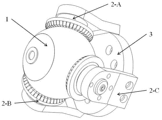
[0031] see figure 1 , the bionic mechanical eyeball based on the spherical ultrasonic motor mainly includes an eyeball (1), three stator mechanisms (2) and a substrate (3).
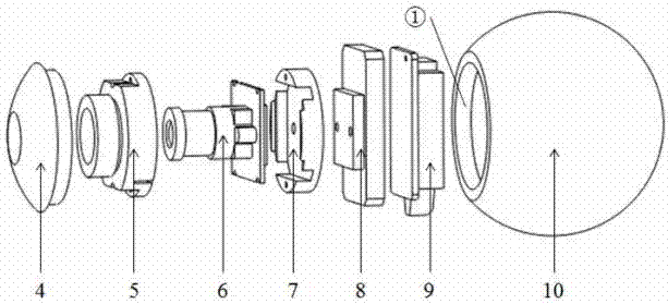
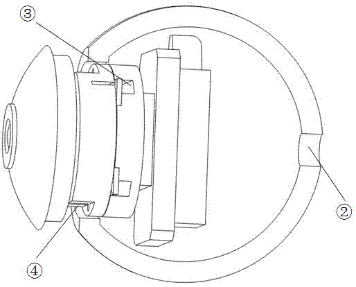
[0032] 1) The specific components of the eyeball (1) are as follows: figure 2 shown. From the surface, it is a small hemispherical front cover (4) and a large hemispherical spherical shell (10) to form the eyeball shell in a threaded manner, but the front end cover (4) and spherical shell must be completed in processing. The seams of the body (10) have a smooth transition. Inside the eyeball housing is a CMOS camera (6) and an attitude sensor (9) tightly fixed by the attitude sensor base (8), camera base (7) and camera compression cover (5). In order to allow these components to pass through the narrow threaded holes (①) of the ball housing (10), a certain order must be ins...
Embodiment 2
[0035] Embodiment 2: This embodiment is basically the same as Embodiment 1, and the special features are as follows:
[0036] Both the front end cover (4) and the ball housing (10) are made of phenolic resin (code name: PF). The threaded holes provided are M36 fine threaded holes; the CMOS camera (6) adopts a miniature CMOS camera module containing a 1 / 4-inch photosensitive sensor, a wide-angle lens and a special PCB board; the attitude sensor (9) adopts a model of 3DM-GX3-25-OEM's three-axis Attitude Inertial Reference System (AHRS); the attitude sensor base, camera base and camera compression cover are made of lighter hard PVC to reduce the mass and moment of inertia of the eyeball .
Embodiment 3
[0037] Embodiment 3: This embodiment is basically the same as Embodiment 1, and the special features are as follows:
[0038] The axial sectional view of the vibrating stator (11) is as Figure 5 shown. After multiple optimizations such as modal analysis, harmonic response analysis and vibration test, the tooth-shaped annular elastic body (18) has a diameter of the outer gear ring (⑧) of 40mm±4mm, and a diameter of the inner gear ring (⑨) of 30mm±3mm. The tooth height (⑩) is 3mm±0.3mm, and the number of teeth is 40±4. The inner edge (⑦) of each tooth of the toothed annular elastic body (18) will be in line contact with the eyeball (1) and friction transmission. The piezoelectric ceramic sheet (19) is pasted on the back of the tooth-shaped annular elastic body (18) in a reasonable circumferential distribution according to the driving principle of the ultrasonic motor, as shown in Figure 6 shown. The 8 piezoelectric ceramic sheets (19) on the left side between the positive ...
PUM
 Abstract
Description
Claims
Application Information
 - R&D
- Intellectual Property
- Life Sciences
- Materials
- Tech Scout
- Unparalleled Data Quality
- Higher Quality Content
- 60% Fewer Hallucinations
Browse by: Latest US Patents, China's latest patents, Technical Efficacy Thesaurus, Application Domain, Technology Topic, Popular Technical Reports.
© 2025 PatSnap. All rights reserved.Legal|Privacy policy|Modern Slavery Act Transparency Statement|Sitemap|About US| Contact US: help@patsnap.com


