A vehicle automatic emergency brake booster
A technology of automatic emergency braking and booster, which is applied in the direction of brakes, vehicle parts, brake transmission devices, etc., can solve the problems of high cost, and achieve the goal of improving production efficiency, ensuring consistency, thread processing efficiency and low cost Effect
- Summary
- Abstract
- Description
- Claims
- Application Information
AI Technical Summary
Problems solved by technology
Method used
Image
Examples
Embodiment 1
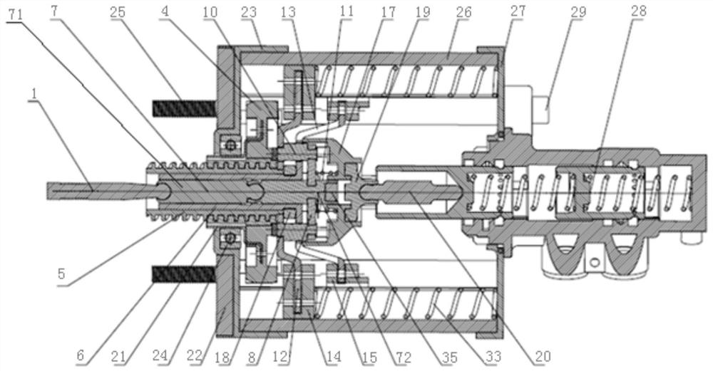
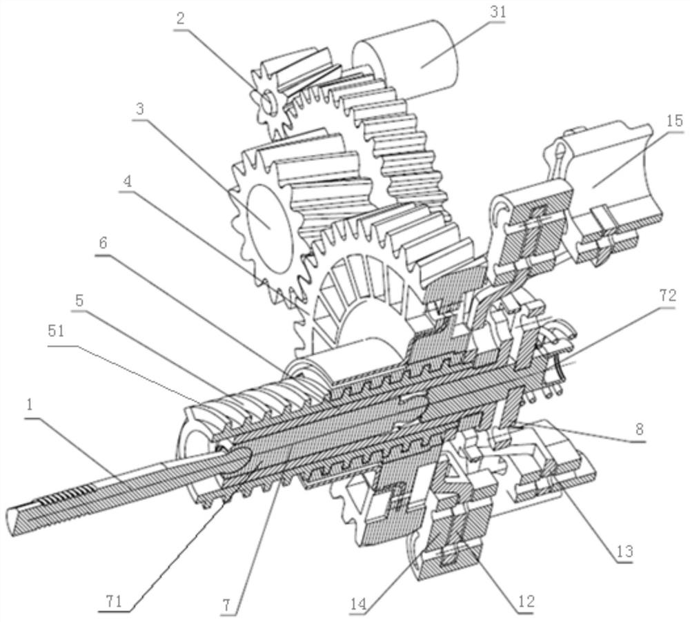
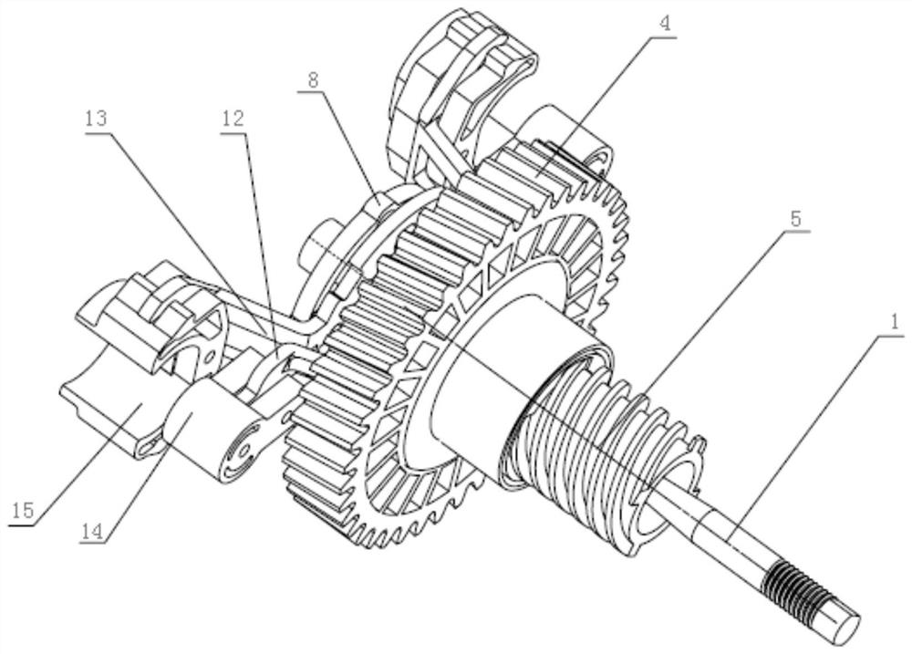
[0082] A vehicle automatic emergency brake booster includes a housing, a pedal force input unit, a pedal force transmission unit, a support and guide unit, an electric power transmission unit, an electric power generation unit, a reset unit and a braking force output unit.
[0083] Such as figure 1 , Figure 9 As shown, the housing includes an upper cover 27, an intermediate housing 26 and a bottom housing 23 connected in sequence; the middle part of the upper cover 27 is provided with a through hole for the columnar input end of the brake master cylinder 28 to pass through; the middle housing 26 Four bolt fixing holes 261 are arranged on the inner side wall (the bolt fixing holes 261 can not only connect but also bear force), the middle housing 26 can be manufactured by drawing molding, die-casting molding, injection molding and other processes; The fixing bolts 29 and the bolt fixing holes 261 are fastened together, and the brake master cylinder 28 and the upper cover 27 ar...
Embodiment 2
[0109] Such as Figure 14 As shown, the difference between the present embodiment and the first embodiment is only that the second elastic element 18 is arranged between the first elastic element 35 and the braking force output element A19, the second elastic element 18 is an annular structure, the first The elastic element 35 can pass through the second elastic element 18 to transmit the braking force to the braking force output element A19.
Embodiment 3
[0111] The difference between this embodiment and Embodiment 1 is only:
[0112] 1. The electric power support 12 and the pedal force support 13 do not share guide rails, but have their own guide rails, that is, the guide rail assembly includes electric power guide rails and pedal force guide rails;
[0113] 2. Both the electric power guide rail and the pedal force guide rail are concave, C-shaped or Ω-shaped in section (such as Figure 15 shown), and the return spring of the electric power support is installed in the electric power guide rail, and the return spring of the pedal force support is installed in the pedal force guide rail.
[0114] All the other structural forms are the same as in Embodiment 1.
PUM
 Abstract
Description
Claims
Application Information
 - R&D
- Intellectual Property
- Life Sciences
- Materials
- Tech Scout
- Unparalleled Data Quality
- Higher Quality Content
- 60% Fewer Hallucinations
Browse by: Latest US Patents, China's latest patents, Technical Efficacy Thesaurus, Application Domain, Technology Topic, Popular Technical Reports.
© 2025 PatSnap. All rights reserved.Legal|Privacy policy|Modern Slavery Act Transparency Statement|Sitemap|About US| Contact US: help@patsnap.com


