Railway steel rail head flaw detection vehicle and usage method thereof

A technology for flaw detection vehicles and rails, which is applied to railway car body parts, railway vehicle shape measuring devices, railway auxiliary equipment, etc., which can solve the problems of affecting driving safety, increasing defects, and low efficiency, so as to improve comfort and convenience , Improving the detection accuracy and improving the detection efficiency

Pending Publication Date: 2020-04-14
NANJING BOKENA AUTOMATION SYST
View PDF0 Cites 2 Cited by
  • Summary
  • Abstract
  • Description
  • Claims
  • Application Information

AI Technical Summary

Problems solved by technology

[0002] Rail defects used in high-speed rail or subway directly affect the operation safety of high-speed rail. During the operation of high-speed rail or subway, the rails will be rubbed and squeezed, causing cracks in the rails. In addition, there will be some trace defects inside the rails when they leave the factory. Under the repeated action of high-speed rail for a long time, it is easy to produce defects such as cracks, slag falling, and fractures, and the internal defects of the rail will gradually increase. Under the action of fatigue stress, it is very easy to break and seriously affect driving safety. Therefore, it is necessary to regularly inspect the rails. , detect cracks and shrinkage defects on the surface of the rail head through the eddy current of the detection probe
In the prior art, the defects of the straight rail section can be detected by using a large locomotive inspection vehicle to walk on the straight rail. However, when performing damage inspection on the point rail of the turnout that enters and exits the station, due to the curved part of the point rail of the turnout, a large locomotive The detection vehicle cannot detect the damage of the curved part. When detecting the point rail part of the switch, it is detected by manual detection with a portable detector, which is inefficient and easy to miss.

Method used


Image

  • Railway steel rail head flaw detection vehicle and usage method thereof
  • Railway steel rail head flaw detection vehicle and usage method thereof
  • Railway steel rail head flaw detection vehicle and usage method thereof

Examples


Embodiment Construction

[0038] In order to further understand the content of the present invention, the present invention will be described in detail below in conjunction with specific examples.

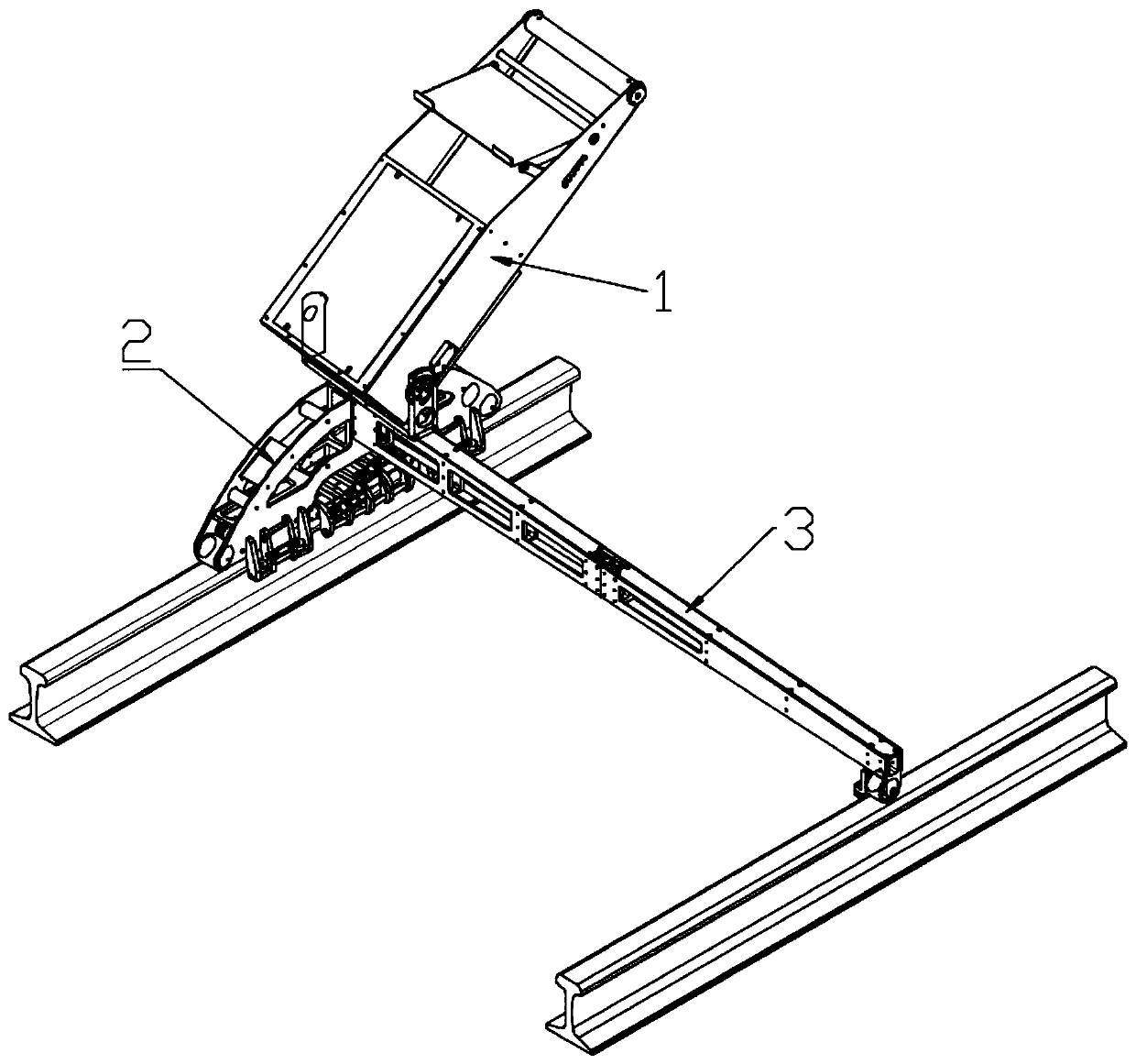
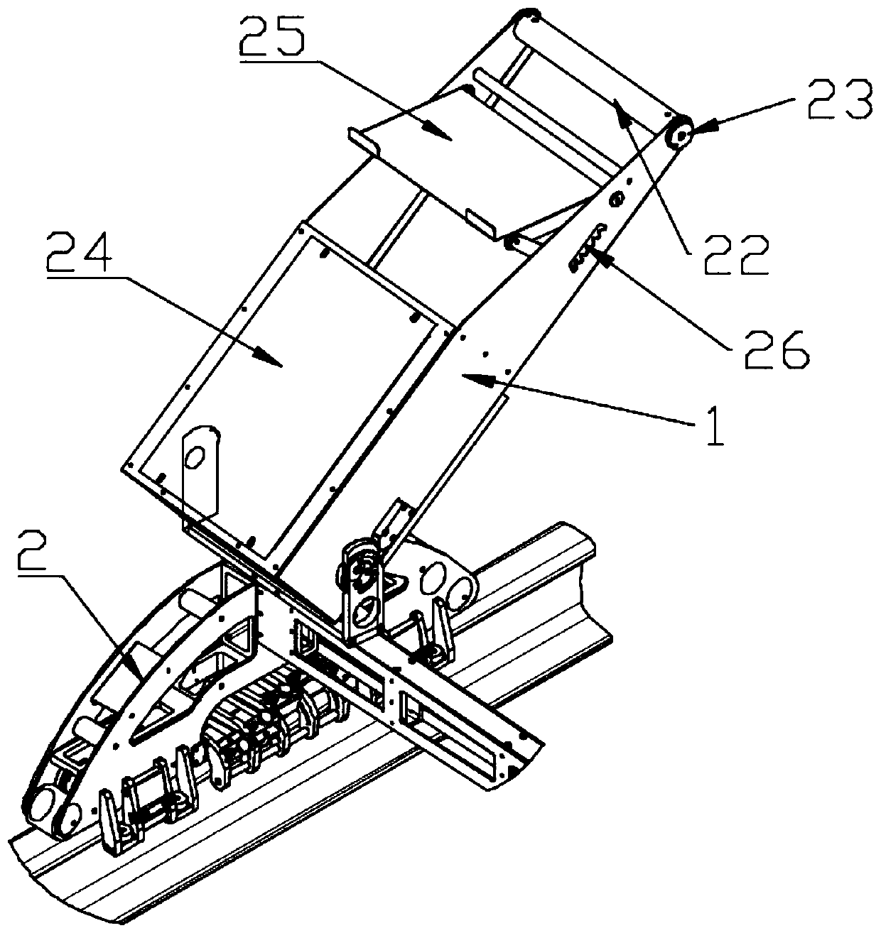
[0039] like Figure 1-14 As shown, according to an embodiment of the railway rail head flaw detection vehicle provided by the present invention, it includes a flaw detector 24 and a pitching frame 1, and the flaw detector 24 is installed on the pitching frame 1, and also includes an arc frame 2, a beam 3, The probe position adjustment assembly and the side wheel assembly, the side wall of the arc frame 2 is fixedly connected with one end of the crossbeam 3, the first horizontal wheels are respectively installed at both ends of the bottom of the arc frame 2, and the arc frame 2 The middle part of the probe position adjustment assembly is installed, and the two ends of the bottom of the inner side wall of the arc frame 2 are respectively fixed with the side wheel assembly. The side wheel assembly includes a m...


PUM


Abstract

The invention relates to a railway steel rail head flaw detection vehicle and a usage method thereof. The device comprises an arc-shaped frame, a cross beam, a probe position adjusting assembly and aside wheel assembly, one side wall of the arc-shaped frame is fixedly connected with one end of the cross beam, first horizontal wheels are installed at the two ends of the bottom of the arc-shaped frame respectively, the probe position adjusting assembly is installed in the middle of the arc-shaped frame, the side wheel assemblies are fixed to the two ends of the bottom of the inner side wall ofthe arc-shaped frame respectively, and each side wheel assembly comprises a magnet base and a first side wheel frame. In the detection walking process, the first side wheel is tightly attached to theinner side face of the steel rail all the time and does not shake, it is guaranteed that the detection portion of each probe does not deviate, the detection accuracy is improved, the multiple probes are integrated, the vulnerable surface of the steel rail can be covered, and therefore the detection efficiency is greatly improved.

Description

technical field [0001] The invention relates to the technical field of rail detection, in particular to a railway rail head flaw detection vehicle and a method for using the same. Background technique [0002] Rail defects used in high-speed rail or subway directly affect the operation safety of high-speed rail. During the operation of high-speed rail or subway, the rails will be rubbed and squeezed, causing cracks in the rails. In addition, there will be some trace defects inside the rails when they leave the factory. Under the repeated action of high-speed rail for a long time, it is easy to produce defects such as cracks, slag falling, and fractures, and the internal defects of the rail will gradually increase. Under the action of fatigue stress, it is very easy to break and seriously affect driving safety. Therefore, it is necessary to regularly inspect the rails. , the cracks and shrinkage defects on the surface of the rail head are detected by the eddy current generate...

Claims


Application Information

Patent Timeline
Patent Type & Authority Applications(China)
IPC IPC(8): B61K9/10G01N27/90G01N27/9013G01N27/904
CPCB61K9/10G01N27/902
Inventor 徐中山刘卫锋郭有文杨勇田
Owner NANJING BOKENA AUTOMATION SYST
Why Eureka
Try Eureka