
Road water absorption cleaning equipment

A technology for cleaning equipment and roads, applied in road surface cleaning, cleaning methods, construction, etc., can solve problems such as accumulation of water to form thin ice, drainage of accumulation of water, traffic accidents, etc., to achieve convenient drainage, avoid icing, and avoid traffic accidents Effect

Active Publication Date: 2020-04-14
山东新建投建设工程质量检测有限公司
View PDF17 Cites 9 Cited by
  • Summary
  • Abstract
  • Description
  • Claims
  • Application Information

AI Technical Summary

Problems solved by technology

[0005] In order to overcome the shortcomings that the drainage pipes may not be able to drain the accumulated water on the road in time, resulting in some remaining water on the road. In winter, the remaining accumulated water will form thin ice, causing the road surface to slip and cause traffic accidents. Therefore, , the technical problem of the present invention is to provide a road water-absorbing cleaning device that can avoid the freezing of road water and avoid causing traffic accidents

Method used


Image

  • Road water absorption cleaning equipment
  • Road water absorption cleaning equipment
  • Road water absorption cleaning equipment

Examples


Embodiment 1

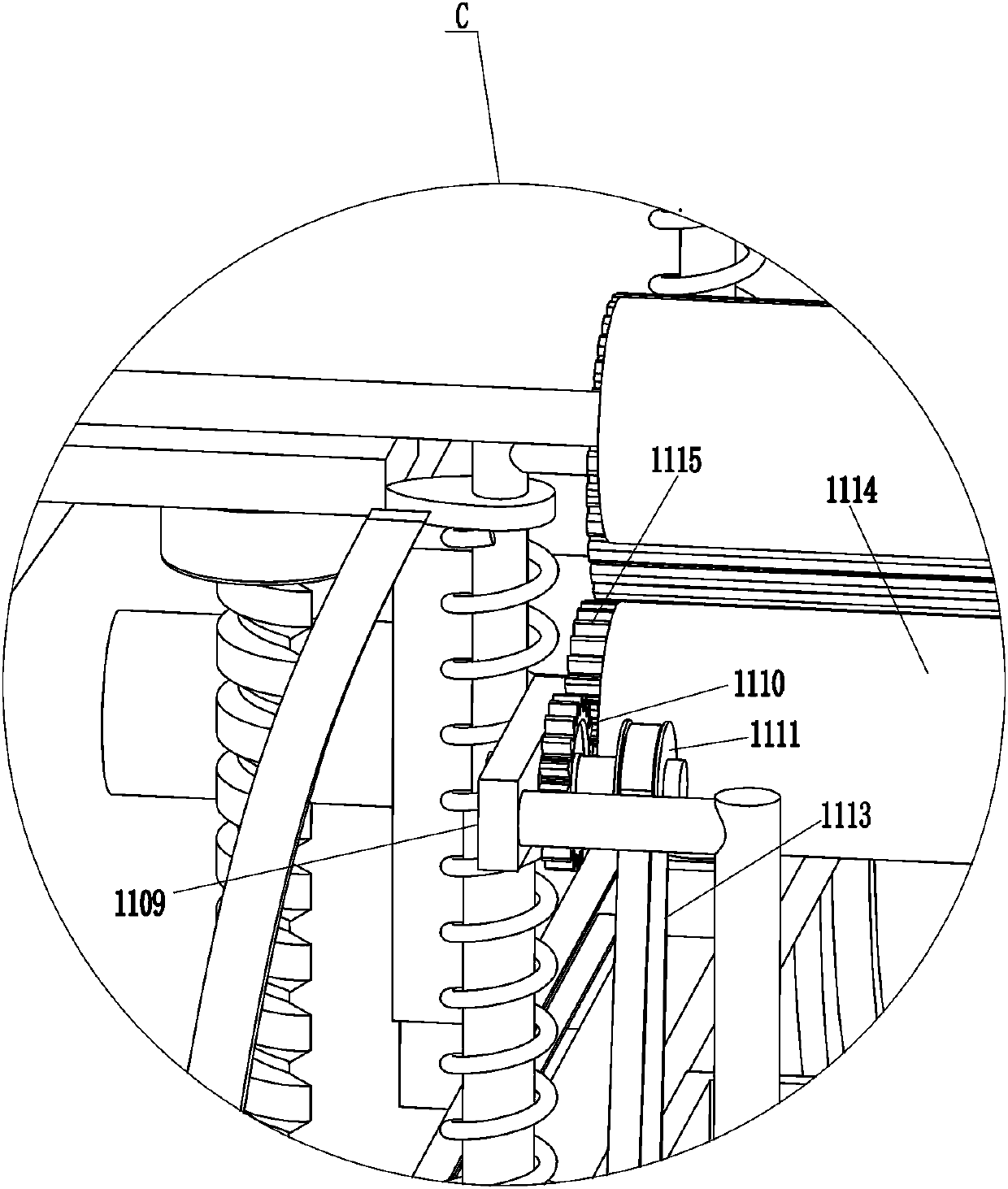
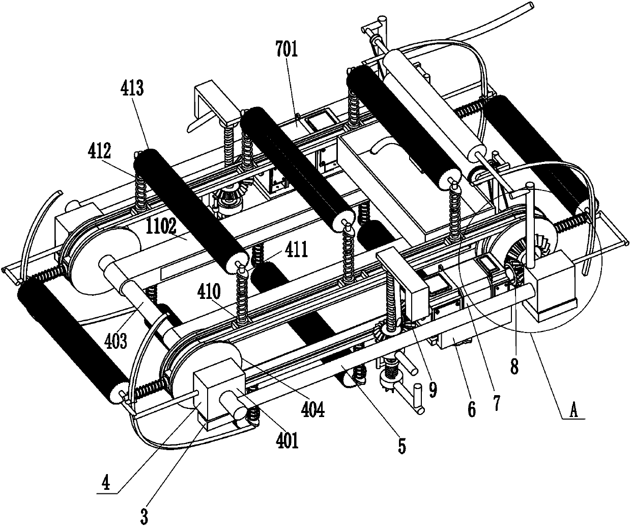
[0030] A road suction cleaning equipment, such as Figure 1-11 As shown, it includes hanging body 1, block 3, cleaning assembly 4, connecting rod 5, first support plate 6, double-axis motor 7, single-axis motor 701, second bevel gear 8, third bevel gear 9, lifting Assembly 10 and dehydration assembly 11, there is an opening 2 on the trailer body 1, two stoppers 3 are connected to the front and rear sides of the opening 2, a cleaning assembly 4 is installed on the stopper 3, and two connection blocks are connected to the cleaning assembly 4. Rod 5, the bottoms of the two connecting rods 5 are welded with a first support plate 6, a biaxial motor 7 is installed on the first support plate 6 on the front side through bolts, and a single shaft motor 7 is installed on the first support plate 6 on the rear side through bolts. Shaft motor 701, the third bevel gear 9 is installed on the output shaft of the single-axis motor 701, the third bevel gear 9 is also installed on the output sha...

Embodiment 2

[0039] On the basis of Example 1, such as Figure 9-10 As shown, control valve 12, storage tank 13, water pump 14 and water pipe 15 are also included, control valve 12 is installed at the bottom of collection box 1107, storage tank 13 and water pump 14 are installed by bolts on the right side of trailer body 1 top, storage tank 13 is located at the front side of the water pump 14, the water pump 14 communicates with the storage tank 13, and the control valve 12 communicates with the water pump 14 through the water pipe 15.

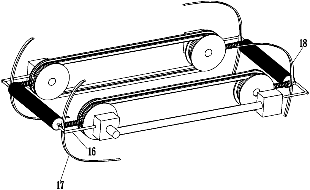
[0040] Also includes a third support frame 16, a first limit bar 17 and a second limit bar 18, the outside of the guide block 401 on the left and right sides is connected with a third support frame 16, and the left end of the third support frame 16 on the left side is connected with a The first limiting bar 17 and the second limiting bar 18 are connected to the right end of the third support frame 16 on the right side.

[0041] When the control valve 12 d...


PUM


Abstract

The invention relates to cleaning equipment, in particular to road water absorption cleaning equipment. According to the road water absorption cleaning equipment, road accumulated water can be prevented from being frozen, and traffic accidents can be avoided. The road water absorption cleaning equipment comprises a trailer body, a stop block, a cleaning assemblies, connecting rods and the like. The trailer body is provided with an opening, at least two check blocks are fixedly connected to each of the two sides in the opening, the cleaning assembly is installed on each check block, the cleaning assemblies are used for cleaning a road and absorbing water, and two connecting rods are connected to the cleaning assemblies. According to the road cleaning equipment, a road can be cleaned and water can be absorbed through the cleaning assemblies, so that accumulated water on the road can be treated in time, the accumulated water on the road is prevented from being frozen, traffic accidents can be avoided, water on the cleaning assembly can be squeezed out through the cleaning assemblies, and the cleaning assemblies can absorb water more effectively.

Description

technical field [0001] The invention relates to a cleaning device, in particular to a road water-absorbing cleaning device. Background technique [0002] Roads are infrastructure for various vehicles and pedestrians, including urban roads, country roads, forestry roads, etc. When it rains for a long time, it will cause water accumulation on the road, and the water will soak the pavement material for a long time, which will lead to the strength of the pavement material. Reduce and accelerate the aging rate of materials, thereby affecting the life of the road. [0003] At present, the accumulated water on the road is generally discharged into lakes or rivers through drainage pipes installed underground. However, when there is too much water on the road, the drainage pipe may not be able to drain the accumulated water on the road in time, resulting in residual water on the road. Some of the accumulated water, in winter, the remaining accumulated water will form thin ice, causi...

Claims


Application Information

Patent Timeline
Patent Type & Authority Applications(China)
IPC IPC(8): E01H1/10
CPCE01H1/108
Inventor 李远倡
Owner 山东新建投建设工程质量检测有限公司
Learn More