Anode gas circulating fan for fuel cell system

A fuel cell system and anode gas technology, applied in liquid fuel engines, electrical components, components of pumping devices for elastic fluids, etc., can solve the problems of series connection, single structure, and low efficiency

Pending Publication Date: 2021-09-10
YANSHAN UNIV
View PDF0 Cites 0 Cited by
  • Summary
  • Abstract
  • Description
  • Claims
  • Application Information

AI Technical Summary

Problems solved by technology

[0002] Fuel cell system refers to a power generation system with fuel cell as the core, fuel supply and circulation system, oxidant supply system, water/heat management system, control system, etc. A single fuel cell stack cannot be used for power generation, and the circulation fan It is an indispensable part of the fuel cell system. Most of the existing anode gas circulation fans are Roots-type fans, which are large in size and low in efficiency. The emitters are connected in series and must be connected in parallel, which makes the installation and layout of the entire system very complicated, high in cost and poor in safety
In addition, lubricating oil is needed to lubricate the driving gear in the Roots-t...

Method used


Image

  • Anode gas circulating fan for fuel cell system
  • Anode gas circulating fan for fuel cell system
  • Anode gas circulating fan for fuel cell system

Examples


Embodiment 1

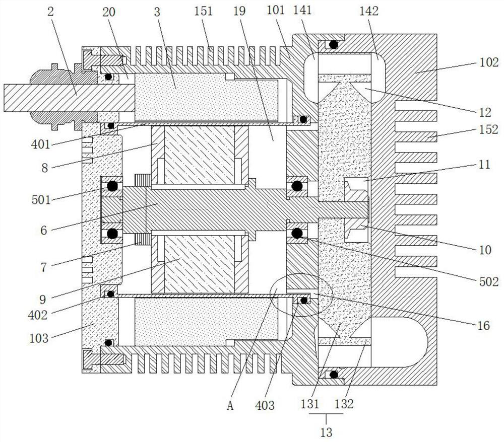
[0038] The operator first installs and fixes the rear cover 103 and the motor casing 101, then installs the stator 3 plastic-sealed with epoxy resin into the inside of the motor casing 101, and then installs the terminal 2 on one end of the motor casing 101 , and between the stator 3 and the terminal 2 are electrically connected, the middle part of the first bearing 501 of the rear cover 103 and the middle part of the second bearing 501 of the motor casing 101 are inserted and fixed with the motor shaft 6, and the middle part of the motor shaft 6 A rotor 9 is installed, and balance weights 8 are installed and fixed on both sides of the rotor 9 through fastening nuts 7;

[0039] One end of the motor shaft 6 is installed and fixed with the impeller 13 through the impeller fastening bolt 10, and the impeller 13 is located inside the impeller groove 12, and the gasket is eliminated, wherein the impeller 13 and the shoulder of the motor shaft 6 fit together, and the shaft of the mot...

Embodiment 2

[0044] Wherein, one side of the motor casing 101 is provided with an arc-shaped flow channel a141, and the flow channel a141 is directly opened on the motor casing 101, which can well reduce the overall size of the circulating fan. There is a flow channel b142 on the side, which can better reduce the local kinetic energy loss. This circulation fan can better improve the work efficiency by adopting double-sided flow channels, and the double-sided flow channels can maintain the pressure balance between the two sides of the impeller 13 , reduce the axial force, thereby improving the service life of the bearing;

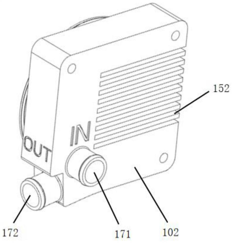
[0045] Further, one side of the flow channel b142 is respectively provided with an air inlet 171 and an air outlet 172 perpendicular to each other, and the junction of the air inlet 171 and the flow channel b142 is an upturned arc transition, which can reduce local kinetic energy loss, The air outlet 172 is designed along the direction of the flow channel b142, which can...

Embodiment 3

[0047] The waterproof bolt groove 11 is directly arranged inside the impeller 13, so that when the head of the circulating fan is placed upside down, the liquid water will form water accumulation in the fan casing 102, reducing the load on the motor, thereby avoiding the overload of the motor occur;

[0048] Wherein, the impeller 13 includes air guide ribs 131 and blades 132, the blades 132 are arranged obliquely clockwise along the central position of the impeller 13, and the included angle between the blades 132 and the central position of the impeller 13 is 1°-85°, and the air guide ribs 131 Cooperating with the blades 132 can guide the direction of the airflow and avoid energy loss caused by local backflow, thereby greatly improving the working efficiency of the impeller 13;

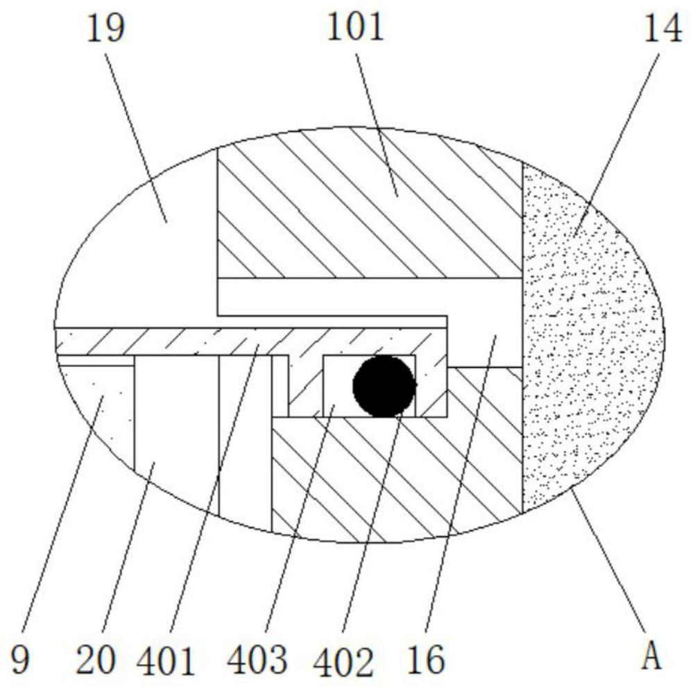
[0049] One side of the motor casing 101 penetrates the inside of the motor rotor air cavity 19 and the impeller groove 12 through the vent hole 16. On the one hand, the internal pressure of the motor...


PUM


Abstract

The invention relates to the technical field of fuel cell systems, in particular to an anode gas circulating fan for a fuel cell system. The anode gas circulating fan comprises a motor casing and a wiring terminal, a rear cover and a fan casing are arranged on the two sides of the motor casing, a motor shaft is inserted between a first bearing and a second bearing, a rotor, a fastening nut and a balance block are installed in the middle of the motor shaft, a stator is installed on the outer side of the rotor, and an impeller is fixedly installed at one end of the motor shaft through an impeller fastening bolt. In the anode gas circulating fan, a waterproof bolt groove is formed in the impeller, and water accumulation of the fan casing is avoided; by adopting flow channels on the two sides and additionally installing vent holes, the pressure in the motor and the pressure at the impeller can be balanced, the service life of the bearings is prolonged, meanwhile, liquid water at the motor can be conveniently discharged through the vent holes, and water accumulation and icing are reduced; an isolation sleeve can prevent hydrogen from flowing to the stator, and the risk of explosion is avoided; and water accumulation in the fan in the fan running process is avoided through a drainage hole, and therefore the overall stability and safety of the circulating fan are improved.

Description

technical field [0001] The invention relates to the technical field of fuel cell systems, in particular to an anode gas circulation fan for a fuel cell system. Background technique [0002] Fuel cell system refers to a power generation system with fuel cell as the core, fuel supply and circulation system, oxidant supply system, water / heat management system, control system, etc. A single fuel cell stack cannot be used for power generation, and the circulation fan It is an indispensable part of the fuel cell system. Most of the existing anode gas circulation fans are Roots-type fans, which are large in size and low in efficiency. The transmitters must be connected in series and must be connected in parallel, which makes the installation and layout of the entire system very complicated, high in cost and poor in safety. In addition, lubricating oil is needed to lubricate the driving gear in the Roots-type blower, but since the fuel cell system must work in an oil-free environme...

Claims


Application Information

Patent Timeline
IPC IPC(8): F04D25/06F04D29/26F04D29/66F04D29/40F04D29/58H02K5/04H02K5/10H02K7/14
CPCF04D25/06F04D29/26F04D29/263F04D29/662F04D29/403F04D29/582F04D29/5806H02K5/04H02K5/10H02K7/14H02K2205/09
Inventor 王建涛
Owner YANSHAN UNIV
Why Eureka
Try Eureka