Turning motion structure and multi-layer food baking tunnel furnace

A technology of moving structure and tunnel oven, which is applied in food oven, baking, food science, etc. It can solve the problems of high energy consumption, affecting food processing efficiency, and small size of baking tunnel oven.

Pending Publication Date: 2020-04-17
广州浩胜食品机械有限公司
View PDF0 Cites 3 Cited by
  • Summary
  • Abstract
  • Description
  • Claims
  • Application Information

AI Technical Summary

Problems solved by technology

[0002] The existing baking tunnel furnace is small in size, and the food is conveyed through a single-layer conveyor belt. The food is baked during the conveying process, but the working efficiency of the conveying and baking method is low, and th

Method used


Image

  • Turning motion structure and multi-layer food baking tunnel furnace
  • Turning motion structure and multi-layer food baking tunnel furnace
  • Turning motion structure and multi-layer food baking tunnel furnace

Examples


Embodiment 1

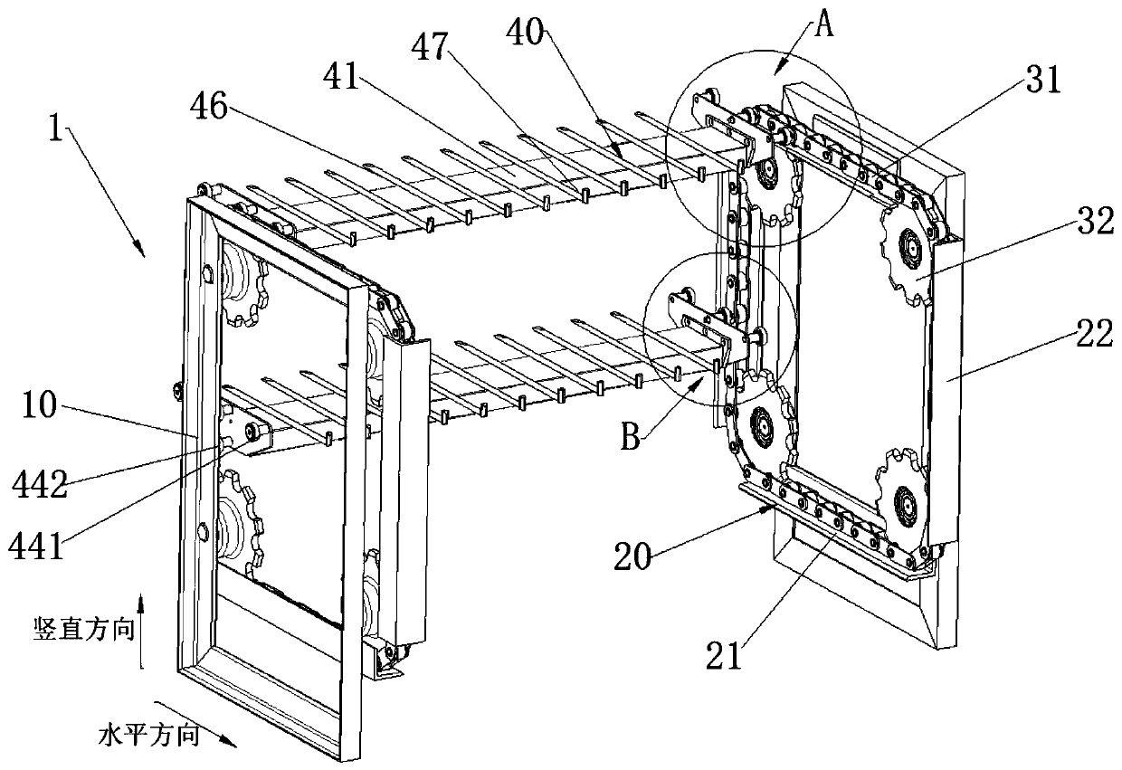
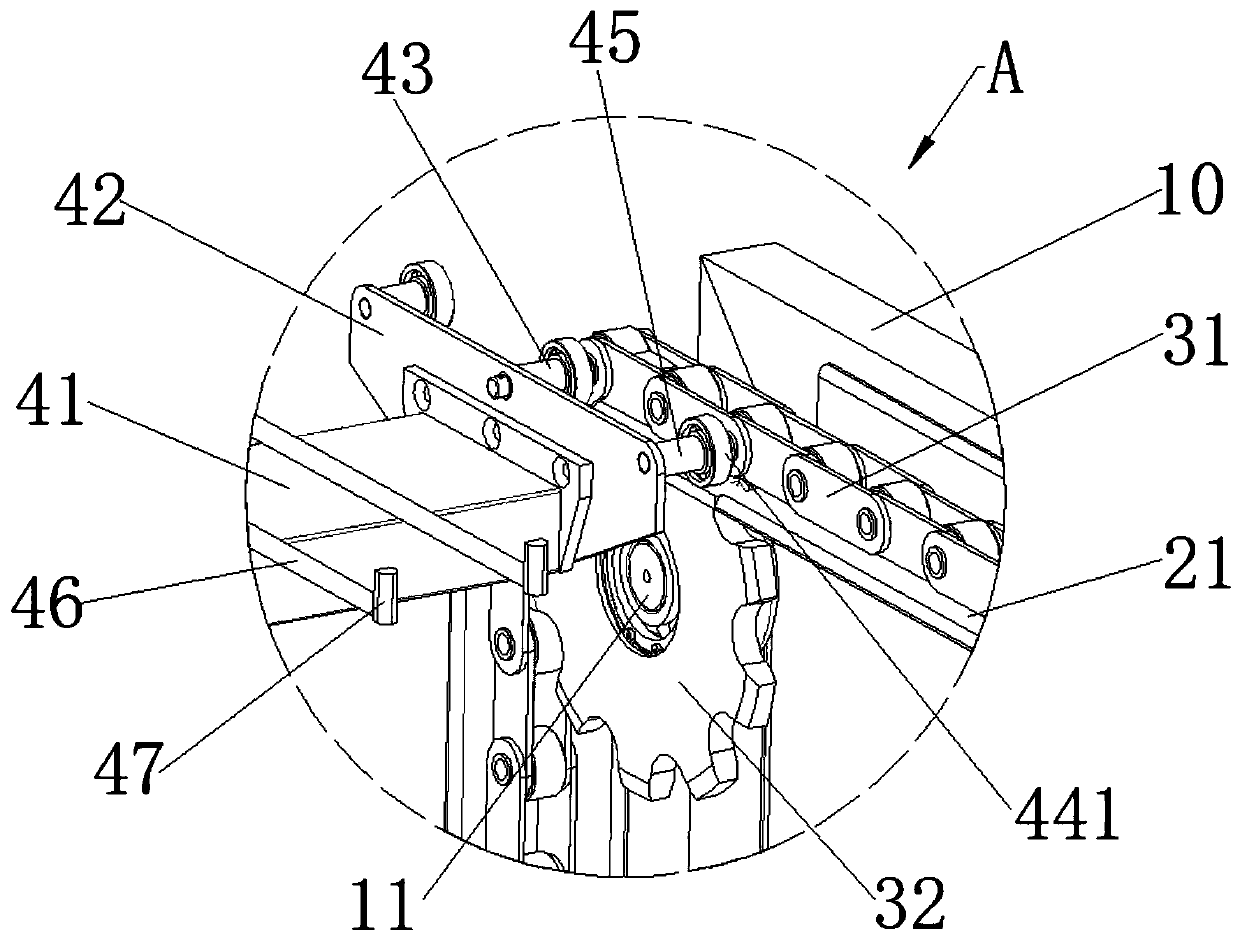
[0013] See Figure 1-4 As shown, the present invention provides a turning structure 1 , which includes a frame 10 , a guide rail 20 , a chain 31 , a bracket 40 and a sprocket 32 ​​.

[0014] The two sets of frames 10 are vertically arranged opposite each other, the bracket 40 is located between the two sets of frames 10 , and the guide rails 20 , chains 31 and sprockets 32 are connected by the frames 10 .

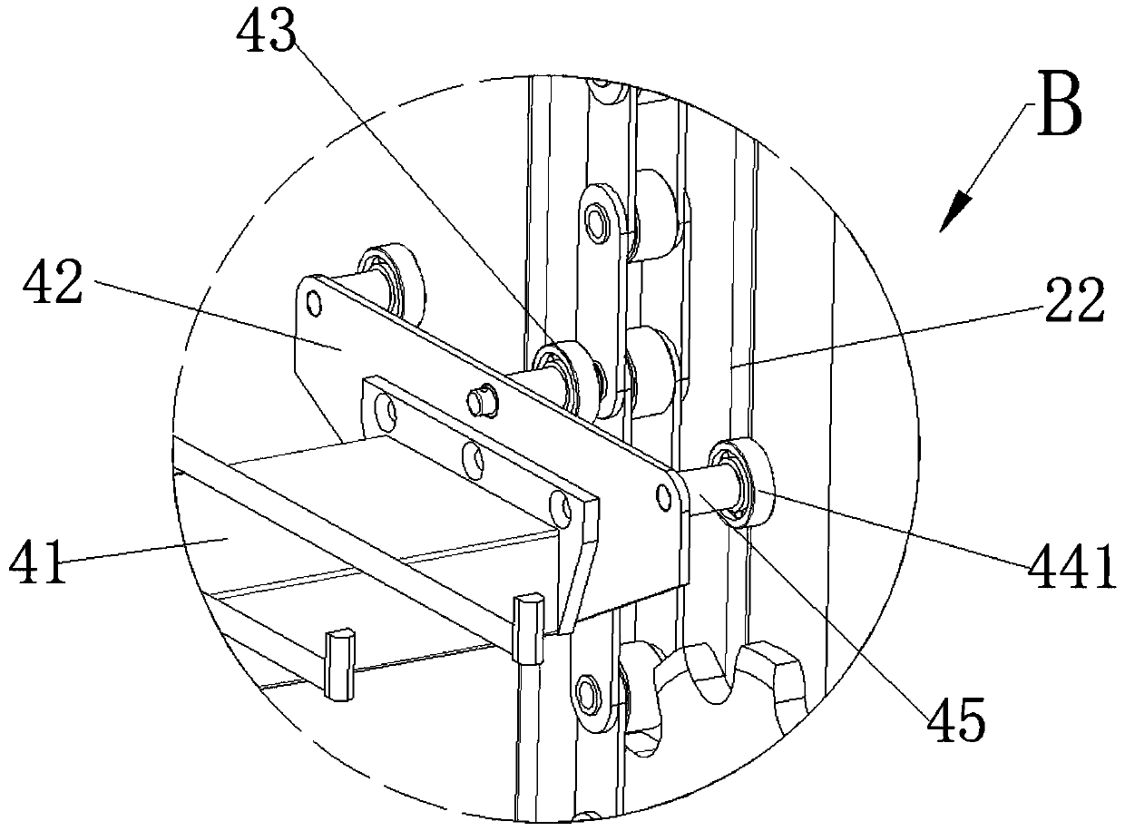
[0015] The guide rail 20 is fixedly arranged on the frame 10 , and the guide rail 20 includes a horizontal guide rail 21 and a vertical guide rail 22 , so as to guide the movement of the bracket 40 in the horizontal direction and the vertical direction.

[0016] The sprocket 32 ​​is rotatably connected with the rotating shaft 11 fixedly arranged on the frame 10. A plurality of sprockets 32 are arranged along the horizontal direction and the vertical direction of the frame 10 respectively. The chain 31 is connected with the sprocket 32 ​​by transmission. Drive the chain 31 ...

Embodiment 2

[0023] refer to Figure 4 As shown, this embodiment provides a multi-layered food baking tunnel oven, which includes the turning structure 1 provided in Embodiment 1, and also includes a conveyor belt 2 , an output belt 3 , a hydraulic cylinder 4 and a fixed plate 5 .

[0024] The baking chamber 6 is formed by the insulation board 61, the turning motion structure 1, the hydraulic cylinder 4 and the fixed plate 5 are accommodated in the baking chamber 6, and the temperature insulation board 62 is arranged in the baking chamber 6, and the temperature insulation board 62 is arranged along the horizontal direction, and the baking chamber 6 is divided into multi-layer passages 63 in the vertical direction by the heat insulating plate 62, and the baking pan is driven by the turning motion structure 1 to carry out horizontal or vertical direction in the multi-layer passage 63. Wherein, those skilled in the art can select the setting positions of the frame, the sprocket and the chain ...


PUM


Abstract

The invention provides a turning motion structure and a multi-layer food baking tunnel furnace. The turning motion structure comprises frames, guide rails, chains, support frames and chain wheels, wherein the guide rails are fixedly arranged on the frames and comprise horizontal guide rails and vertical guide rails; each chain wheel is rotatably connected with a rotating shaft fixedly arranged ona frame; a plurality of the chain wheels are arranged along the horizontal direction and the vertical direction of the frames correspondingly; the chains are in transmission connection with the chainwheels and are driven to move by rotation of the chain wheels; each support frame comprises a cross beam and supporting plates arranged at two ends of a cross beam; transmission rollers and guide rollers are arranged on supporting plates; the transmission rollers are fixedly connected with the chains; and the guide rollers can be propped against the guide rails. The turning motion structure provided by the invention has the following advantages: through transmission of the chain wheels and the chains, the support frames can be driven to move along a vertical or horizontal direction; through the guiding rollers, the support frames can move stably on the guide rails; thus, baking trays are prevented from tipping over; multi-layer baking of food in a vertical direction is realized; and the baking efficiency of a tunnel furnace is improved.

Description

technical field [0001] The invention relates to the technical field of food processing equipment, in particular to a turning motion structure and a multi-layer food baking tunnel furnace. Background technique [0002] The existing baking tunnel furnace is small in size, and the food is conveyed through a single-layer conveyor belt. The food is baked during the conveying process, but the working efficiency of the conveying and baking method is low, and the single-baked food The quantity is limited, which affects the efficiency of food processing and consumes a lot of energy. If the quantity of baked food is increased, the length of the conveyor belt needs to be extended to support more baked food. Therefore, how to improve the baking efficiency of the tunnel furnace without expanding the volume of the tunnel furnace is a technical problem to be solved urgently by those skilled in the art. Contents of the invention [0003] In view of this, the technical problem to be solve...

Claims


Application Information

Patent Timeline
IPC IPC(8): A21B1/48A21B3/00
CPCA21B1/48A21B3/00
Inventor 邱木圳
Owner 广州浩胜食品机械有限公司
Why Eureka
Try Eureka