Rail bolt grease brush coating device
A bolt and grease technology, applied in the field of rail bolt grease brushing device, can solve the problems of uneven grease application and long time consumption, and achieve the effect of speeding up and convenient use.
- Summary
- Abstract
- Description
- Claims
- Application Information
AI Technical Summary
Problems solved by technology
Method used
Image
Examples
Embodiment 1
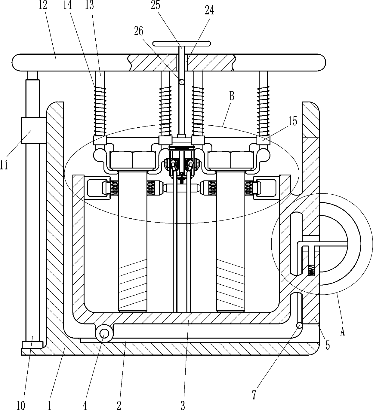
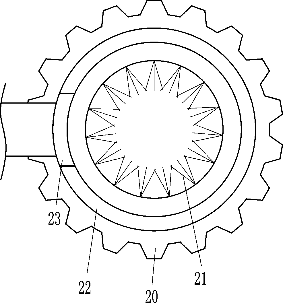
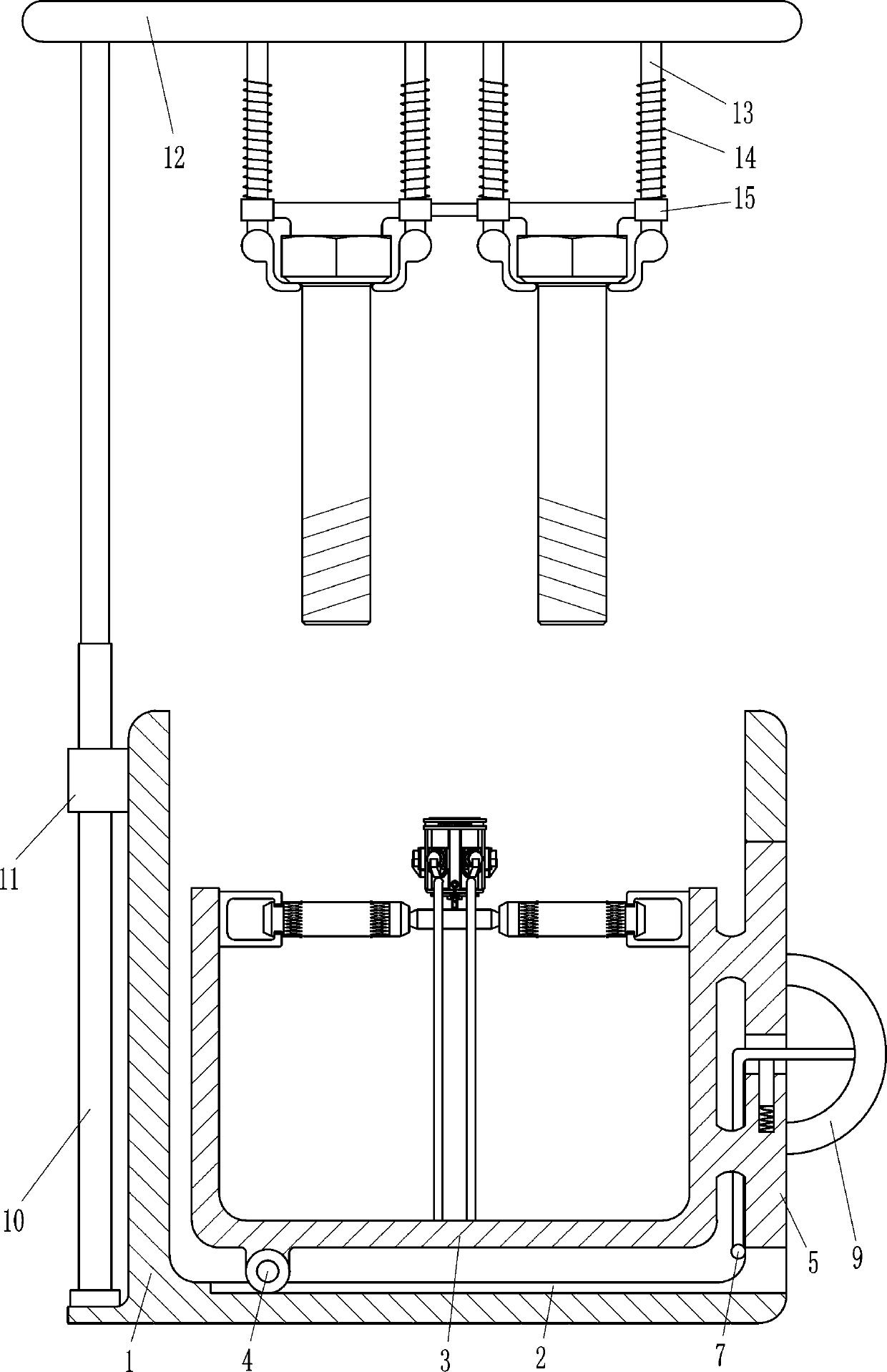
[0020] Such as figure 1 , 2 , 3, 4 and 5, a rail bolt grease brushing device includes an outer shell 1, a grease placement part, a lifting part, a bolt fixing part and a brushing part, and a grease placement part is slidably installed in the outer shell 1 , the outer casing 1 is equipped with a lifting part that is lifted and lowered by pulling, and a bolt fixing part that fixes the bolt by lifting is installed on the lifting part, and a brush that brushes the bolt with grease by rotating is provided in the grease placement part. part.
[0021] Such as figure 1 , 2 As shown in and 3, the grease placement parts include an inner casing 3, a wheel 4, a baffle plate 5, a special-shaped rod 7, a first spring 8 and a pull ring 9, and the inner bottom of the outer casing 1 has a wheel groove 2, and the wheel groove 2 The sliding type is provided with wheels 4, the top of the wheels 4 is connected to the inner casing 3 by screws, the right side of the inner casing 3 is connected t...
Embodiment 2
[0031] Such as figure 2 As shown, on the basis of Embodiment 1, in order to use the device better, it also includes a T-shaped bar 25 and a clamping bar 26. There is a straight guide hole 24 in the center of the top of the lifting plate 12, and a straight guide hole 24 The inner sliding type is connected with a T-shaped bar 25, and the bottom end of the T-shaped bar 25 is connected with the guide sleeve 15 through a rotary joint, and the bottom of the T-shaped bar 25 is welded with a clamping bar 26.
[0032] The working principle of the above embodiment is that when the guide sleeve 15 needs to be pulled to move the fixing bolt upward, the T-shaped bar 25 is directly pulled upwards to drive the clamping rod 26 to move upwards, and when the clamping rod 26 moves upwards to the top of the lifting plate 12, the T-shaped The rod 25 rotates 90°, drives the clamping rod 26 to rotate 90°, makes the clamping rod 26 be stuck on the top of the lifting plate 12, and fixes the guide sle...
PUM
 Abstract
Description
Claims
Application Information
 - R&D
- Intellectual Property
- Life Sciences
- Materials
- Tech Scout
- Unparalleled Data Quality
- Higher Quality Content
- 60% Fewer Hallucinations
Browse by: Latest US Patents, China's latest patents, Technical Efficacy Thesaurus, Application Domain, Technology Topic, Popular Technical Reports.
© 2025 PatSnap. All rights reserved.Legal|Privacy policy|Modern Slavery Act Transparency Statement|Sitemap|About US| Contact US: help@patsnap.com


