Counter-weight mechanism and vertical loop system

A vertical looper and looper technology, applied in the field of counterweight mechanism and vertical looper system, can solve the problems of the limitation of the lifting space of the looper car, affecting the strip steel storage, occupying space, etc. The effect of saving space and storing more strip material

Inactive Publication Date: 2020-04-17
ZHAOQING HONGWANG METAL IND
View PDF6 Cites 0 Cited by
  • Summary
  • Abstract
  • Description
  • Claims
  • Application Information

AI Technical Summary

Problems solved by technology

[0002] When the existing stainless steel plate deep processing production line is changing coils, the entire production line needs to be shut down to wait for the coil change, which affects the production efficiency of the stainless steel plate deep processing production line and limits the production capacity of the production line. The quality of deep processing of stainless steel plates is unstable
For this reason, a vertical looper system is needed to enable the entire stainless steel plate deep processing production line to run continuously when changing coils. In a conventional vertical looper system, the looper can be lifted and moved to the In the frame of the looper, there is a guide column structure between the looper and the looper frame. The guide column structure plays a role of stability and balance during the lifting process of the looper, but the guide column structure will occupy the space between the looper and the looper. The space between the frames restricts the lifting space of the looper, which affects the strip storage

Method used


Image

  • Counter-weight mechanism and vertical loop system
  • Counter-weight mechanism and vertical loop system
  • Counter-weight mechanism and vertical loop system

Examples


Embodiment Construction

[0017] Specific embodiments of the present invention will be described in detail below in conjunction with the accompanying drawings. It should be understood that the specific embodiments described here are only used to illustrate and explain the present invention, and are not intended to limit the protection scope of the present invention.

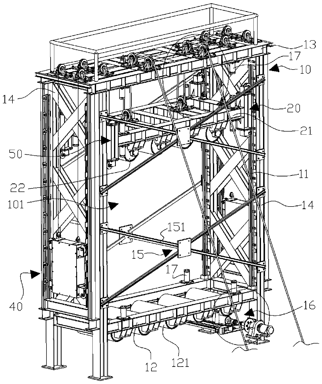
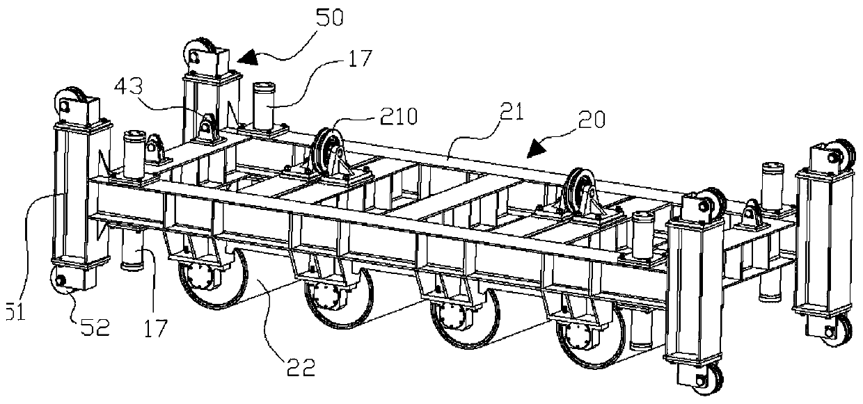
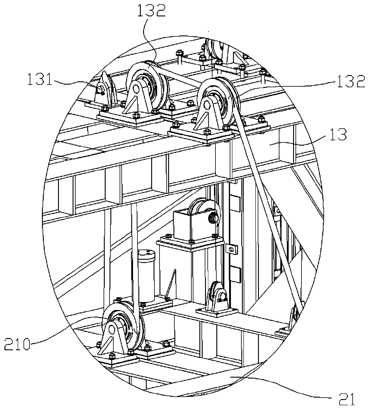
[0018] see figure 1 , Image 6 , a vertical looper system for continuous strip steel storage, which includes a looper frame 10, a looper car 20, a drive mechanism 30 and a counterweight mechanism 40; the looper frame 10 has a The installation space 101 of the set car 20, the looper frame 10 is provided with four lifting rails 11 in the installation space 101, and the four lifting rails 11 are arranged oppositely in pairs, and each lifting rail 11 is correspondingly located at the corner of the installation space 101. The cover frame 10 is fixed with a seat frame 12 at the bottom of the installation space 101, and a plurality of position...


PUM


Abstract

The invention discloses a counter-weight mechanism. The counter-weight mechanism is installed on a loop frame, wherein the loop frame is provided with an installation space provided with a loop car; the loop frame is fixedly provided with a fixed frame at the top of the installation space; the fixed frame is transversally provided with a plurality of counter-weight wheels at the two sides separately; the loop frame is provided with counter-weight rail groups at the two sides separately; and each counter-weight rail group is provided with two counter-weight rails which are oppositely arranged.The counter-weight mechanism comprises two counter-weight blocks and a connection chain, wherein the two counter-weight blocks are oppositely arranged at the two sides of the loop frame; each counter-weight block is correspondingly installed between the two counter-weight rails of the corresponding counter-weight rail group; a plurality of rolling wheels are arranged at the two sides of each counter-weight block separately; each counter-weight block is capable of moving up and down between the two corresponding counter-weight rails through corresponding installation for the corresponding rolling wheels and the corresponding counter-weight rail at the same side; and the connection chain oppositely connects each counter-weight block with the loop car. The counter-weight mechanism and a vertical loop system play the role of stable balance, and balance the weights of the loop car and the stored strip steel.

Description

technical field [0001] The invention relates to the technical field of stainless steel plate deep processing production line, in particular to a counterweight mechanism and a vertical looper system. Background technique [0002] When the existing stainless steel plate deep processing production line is changing coils, the entire production line needs to be shut down to wait for the coil change, which affects the production efficiency of the stainless steel plate deep processing production line and limits the production capacity of the production line. The quality of deep processing of stainless steel plates is unstable. For this reason, a vertical looper system is needed to enable the entire stainless steel plate deep processing production line to run continuously when changing coils. In a conventional vertical looper system, the looper can be lifted and moved to the In the frame of the looper, there is a guide column structure between the looper and the looper frame. The g...

Claims


Application Information

Patent Timeline
Patent Type & Authority Applications(China)
IPC IPC(8): B21C47/24
CPCB21C47/24
Inventor 刘慧丹卢威刘自然缪朴陈元阳鹏
Owner ZHAOQING HONGWANG METAL IND
Why Eureka
Try Eureka