
Coaxial type bending and twisting simultaneous transmission control surface transmission mechanism

A technology of rudder surface transmission mechanism and steering gear, which is applied in the directions of aircraft transmission, aircraft power transmission, aircraft power device, etc. and scattering problems, to achieve the effect of simple and easy assembly positioning, clear load transmission path, and short transmission path

Inactive Publication Date: 2020-04-17
CHENGDU AIRCRAFT INDUSTRY GROUP
View PDF5 Cites 3 Cited by
  • Summary
  • Abstract
  • Description
  • Claims
  • Application Information

AI Technical Summary

Problems solved by technology

[0003] 1) The structure of the rod rocker arm will inevitably cause the transmission mechanism to protrude from the shape of the rudder surface and the shape of the wing surface where it is located. It is necessary to design rectification bulges between the output end of the steering gear and the rudder surface rocker. The effective lift area reduces the control efficiency of the rudder surface and increases the aerodynamic drag during flight;
[0004] 2) The transmission path formed by the rod rocker structure is longer
There are many accessories of the mechanism, on the one hand, it causes the weight of its transmission structure to be large, and on the other hand, it affects its transmission accuracy;
[0005] 3) For aircraft with stealth performance requirements, the front and rear rectification bulges formed by the rod rocker structure will increase unnecessary reflection and scattering, affecting stealth performance

Method used


Image

  • Coaxial type bending and twisting simultaneous transmission control surface transmission mechanism
  • Coaxial type bending and twisting simultaneous transmission control surface transmission mechanism
  • Coaxial type bending and twisting simultaneous transmission control surface transmission mechanism

Examples


Embodiment 1

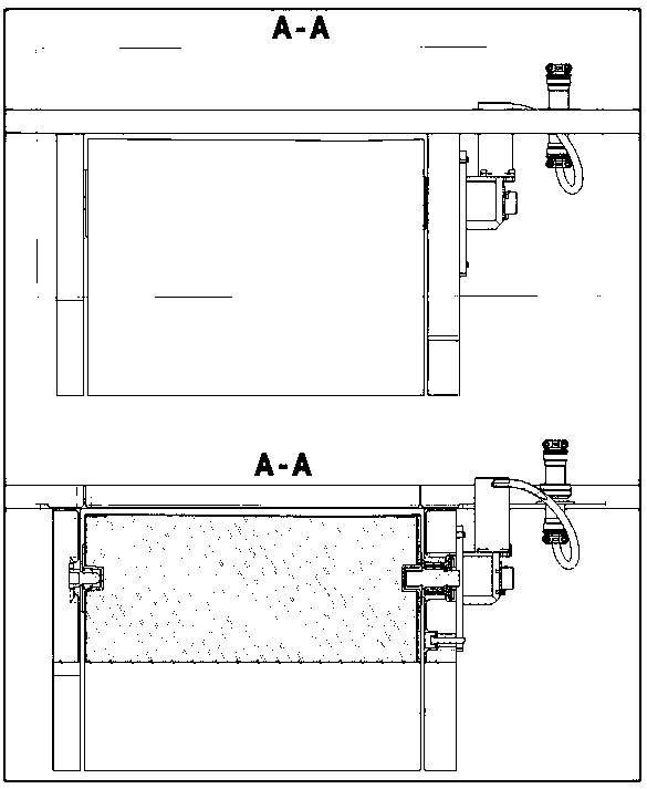
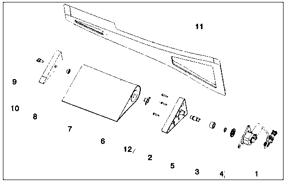
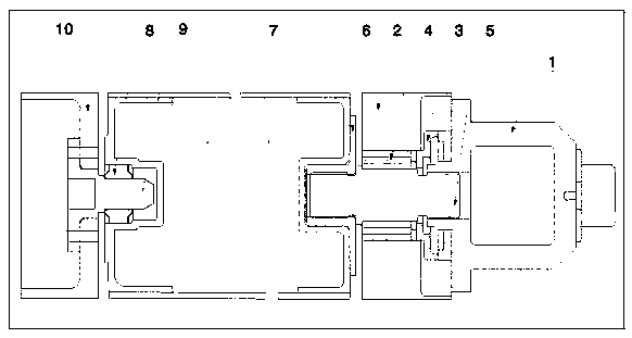
[0036] A coaxial bending and torsion simultaneous transmission rudder surface 7 transmission mechanism is characterized in that: a steering gear 1, a steering gear mounting rib 2, a needle bearing 3, a retaining ring 4, a coupling 5, a transmission spline 6, and a rudder surface 7. Joint bearing 8, shaft pin 9, rudder surface installation rib 10 and body rear beam 11, the steering gear 1 is connected with the coupling 5, the coupling 5 is provided with a needle bearing 3, and the retaining ring The bearing 4 is arranged on the outside of the needle roller bearing 3, and the bearing of the retaining ring 4 is provided with a steering gear installation rib 2, and the steering gear installation rib 2 is connected with a transmission spline 6, and one side of the transmission spline 6 is a rudder surface 7. The rudder surface 7 is provided with a pivot pin 9, the pivot pin 9 is connected with the joint bearing 8, the joint bearing 8 is connected with the rudder surface installation...

Embodiment 2

[0039] A coaxial bending and torsion simultaneous transmission rudder surface 7 transmission mechanism is characterized in that: a steering gear 1, a steering gear mounting rib 2, a needle bearing 3, a retaining ring 4, a coupling 5, a transmission spline 6, and a rudder surface 7. Joint bearing 8, shaft pin 9, rudder surface installation rib 10 and body rear beam 11, the steering gear 1 is connected with the coupling 5, the coupling 5 is provided with a needle bearing 3, and the retaining ring The bearing 4 is arranged on the outside of the needle roller bearing 3, and the bearing of the retaining ring 4 is provided with a steering gear installation rib 2, and the steering gear installation rib 2 is connected with a transmission spline 6, and one side of the transmission spline 6 is a rudder surface 7. The rudder surface 7 is provided with a pivot pin 9, the pivot pin 9 is connected with the joint bearing 8, the joint bearing 8 is connected with the rudder surface installation...

Embodiment 3

[0044] A coaxial bending and torsion simultaneous transmission rudder surface 7 transmission mechanism is characterized in that: a steering gear 1, a steering gear mounting rib 2, a needle bearing 3, a retaining ring 4, a coupling 5, a transmission spline 6, and a rudder surface 7. Joint bearing 8, shaft pin 9, rudder surface installation rib 10 and body rear beam 11, the steering gear 1 is connected with the coupling 5, the coupling 5 is provided with a needle bearing 3, and the retaining ring The bearing 4 is arranged on the outside of the needle roller bearing 3, and the bearing of the retaining ring 4 is provided with a steering gear installation rib 2, and the steering gear installation rib 2 is connected with a transmission spline 6, and one side of the transmission spline 6 is a rudder surface 7. The rudder surface 7 is provided with a pivot pin 9, the pivot pin 9 is connected with the joint bearing 8, the joint bearing 8 is connected with the rudder surface installation...


PUM


Abstract

The invention provides a design scheme of a coaxial type bending and twisting simultaneous transmission control surface transmission mechanism, and aims to solve inherent defects of a common pull rodrocker arm type control surface transmission mechanism for airplanes adopting airfoils with medium and above thicknesses. The mechanism is characterized by comprising a steering engine, a steering engine mounting rib, a needle bearing, a check ring, a coupler, a transmission spline, a control surface, a knuckle bearing, a rotating shaft pin, a control surface mounting rib and a machine body rear beam, wherein the steering engine is connected with the coupler, the needle bearing is arranged on the coupler, a check ring bearing is arranged on the outer side of the needle bearing, the check ringbearing is provided with the steering engine mounting rib, the steering engine mounting rib is connected with the transmission spline, one side of the transmission spline is the control surface, the control surface is provided with the rotating shaft pin, the rotating shaft pin is connected with the knuckle bearing, the knuckle bearing is connected with the control surface mounting rib, and the control surface mounting rib is connected with the machine body rear beam.

Description

technical field [0001] The invention relates to the field of aviation manufacturing, and relates to a coaxial bending and torsion simultaneous transmission rudder surface transmission mechanism. Background technique [0002] At present, the common control rudder transmission form of manned aircraft or medium and large UAVs is the rod rocker transmission mechanism. This form of transmission mechanism can be further divided into the form of the electric steering gear output torque rocker to drive the rudder surface pull rod, or the hydraulic cylinder directly drives the rudder surface rocker, etc. This form of rudder surface transmission has the following disadvantages: [0003] 1) The structure of the rod rocker arm will inevitably cause the transmission mechanism to protrude from the shape of the rudder surface and the shape of the wing surface where it is located. It is necessary to design rectification bulges between the output end of the steering gear and the rudder surfa...

Claims


Application Information

Patent Timeline
IPC IPC(8): B64C13/24B64C13/50
CPCB64C13/24B64C13/50
Inventor 党万腾李宇飞林荣欣方雄陈晓峰胡伯仁熊雅晴
Owner CHENGDU AIRCRAFT INDUSTRY GROUP
Learn More