A presser foot mechanism in a placket machine and its control method
A technology of presser foot mechanism and placket machine, which is applied to the sewing machine's thread cutting mechanism, cloth pressing mechanism, cloth feeding mechanism, etc., which can solve the problems of low automation, low processing efficiency, and poor precision, and achieve the level of automation High, the effect of improving sewing efficiency and sewing precision
- Summary
- Abstract
- Description
- Claims
- Application Information
AI Technical Summary
Problems solved by technology
Method used
Image

Examples
Embodiment 1
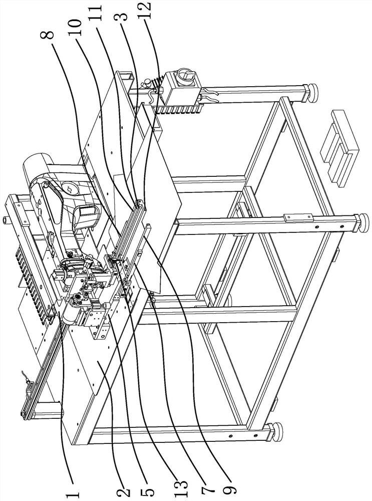
[0038] Such as figure 1 with figure 2 As shown, the fly machine in this embodiment includes a frame 1, a cover plate 2, and a middle knife assembly 13. The frame 1 is fixed with a fixed plate 4 positioned above the cover plate 2. The presser foot mechanism includes side by side and spaced Left connecting arm 5 and right connecting arm 6, the inner ends of left connecting arm 5 and right connecting arm 6 are all pivotally connected on the fixed plate 4, the outer end of left connecting arm 5 is fixedly provided with left clamping arm 7, left clamping arm 7 A strip-shaped left presser foot 9 is arranged on the top, and the outer end of the right connecting arm 6 is fixedly provided with a right clamp arm 8, and the right clamp arm 8 is provided with a strip-shaped right presser foot 10, left presser foot 9 and right presser foot 10 are arranged side by side at intervals; one side of the left presser foot 9 and / or the right presser foot 10 is provided with a rotatable transmiss...
Embodiment 2
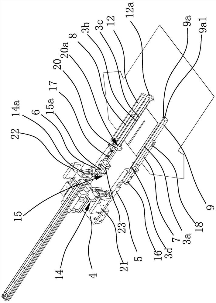
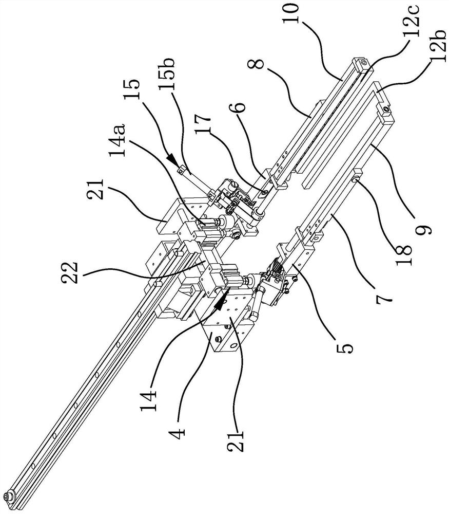
[0045] Such as image 3 with Figure 4As shown, this embodiment is roughly the same as Embodiment 1, the difference is that in this embodiment, both ends of the left presser foot 9 and both ends of the right presser foot 10 are fixed with mounting blocks 20 extending inwardly. The block 20 is provided with a mounting hole 20a, and the left blowing pipe 3a and the right blowing pipe 3b are plugged into the mounting holes 20a of the corresponding two mounting blocks 20 respectively; there are two transmission shafts 11, one of which is rotatably connected to the On the two mounting blocks 20 at the two ends of the left presser foot 9, another power transmission shaft 11 is rotatably connected on the two mounting blocks 20 at the two ends of the right presser foot 10, and the two driving parts 15 also have two and correspond to a power transmission shaft 11 respectively. The cloth pendulum presser foot 12 comprises an L-shaped swing arm one 12b and an L-shaped swing arm two 12c....
Embodiment 3
[0049] This embodiment discloses a method for controlling the presser foot mechanism in a fly machine. The presser foot mechanism in the fly machine is the same as the presser foot mechanism in Embodiment 1 or Embodiment 2 above. The control method includes the following steps:
[0050] a. Place the fabric: When the whole machine is in the initial state, the left presser foot 9, the right presser foot 10 and the cloth pendulum presser foot 12 are lifted up, and a large piece of cloth and the placket cloth are placed;
[0051] b. Sewing thread: After giving the signal to the control system, the driver one 14 drives the outer ends of the left connecting arm 5 and the right connecting arm 6 to swing towards the direction of the cover plate 2, thereby driving the left clamping arm 7, the right clamping arm 8, the left The presser foot 9 and the right presser foot 10 are pressed down, and the cloth pendulum presser foot 12 is also pressed down at the same time. The sewing needles of...
PUM
 Abstract
Description
Claims
Application Information
 - R&D
- Intellectual Property
- Life Sciences
- Materials
- Tech Scout
- Unparalleled Data Quality
- Higher Quality Content
- 60% Fewer Hallucinations
Browse by: Latest US Patents, China's latest patents, Technical Efficacy Thesaurus, Application Domain, Technology Topic, Popular Technical Reports.
© 2025 PatSnap. All rights reserved.Legal|Privacy policy|Modern Slavery Act Transparency Statement|Sitemap|About US| Contact US: help@patsnap.com