A self-cleaning and stabilizing water heater based on the principle of high-temperature degaussing

A self-cleaning, water heater technology, applied in the direction of cleaning heat transfer devices, fluid heaters, rotating equipment cleaning, etc., can solve the problems of unstable water pressure, easy to cover the heating pipe with scale, etc.

Active Publication Date: 2021-08-03
聊城尚贤物资有限公司
View PDF17 Cites 0 Cited by
  • Summary
  • Abstract
  • Description
  • Claims
  • Application Information

AI Technical Summary

Problems solved by technology

[0005] The purpose of the present invention is to solve the problem that the water pressure in the water tank is unstable and the heating pipe is easily covered by scale, and to provide a self-cleaning stabilized water heater based on the principle of high-temperature degaussing that can stabilize the water pressure in the water tank and clean the heating pipe at the same time

Method used


Image

  • A self-cleaning and stabilizing water heater based on the principle of high-temperature degaussing
  • A self-cleaning and stabilizing water heater based on the principle of high-temperature degaussing
  • A self-cleaning and stabilizing water heater based on the principle of high-temperature degaussing

Examples


Embodiment 1

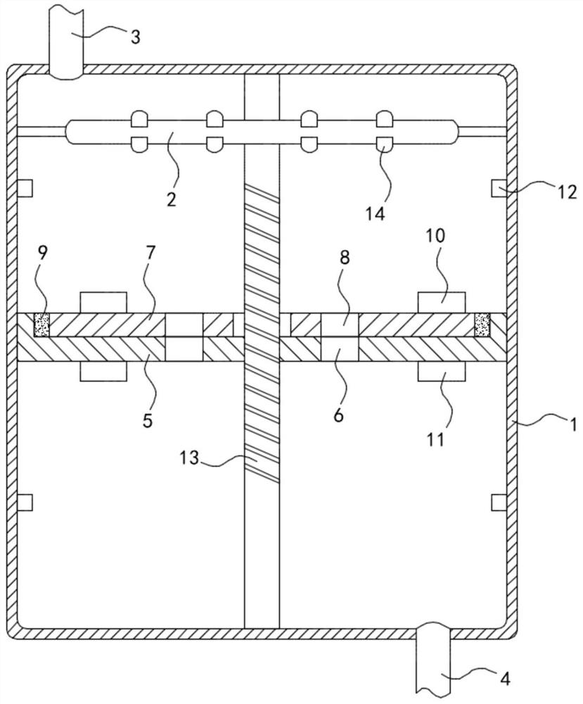
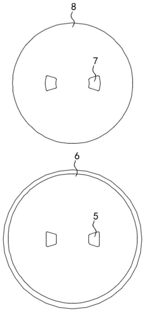
[0022] Such as Figure 1-3 As shown, a self-cleaning and stabilizing water heater based on the principle of high-temperature degaussing includes a box body 1, and a heating device 2 is arranged in the box body 1. The heating device 2 is an annular heating tube, and the annular heating tube is fixedly installed in the box body 1. The top surface, the upper end and the lower end of the box body 1 are fixedly connected with the water inlet pipe 3 and the water outlet pipe 4 respectively, and the inner wall of the box body 1 is connected with the lifting plate 5 in a sealed and sliding manner. It should be noted that the inner wall of the box body 1 is fixed. Two limit rings 12 are connected, and the two limit rings 12 are respectively located above and below the lifting plate 5. The limit rings 12 are used to limit the lifting plate 5 and prevent the lifting plate 5 from hitting the inner top of the box body 1. Damage to surface and inner bottom surface.

[0023] In this embodim...

Embodiment 2

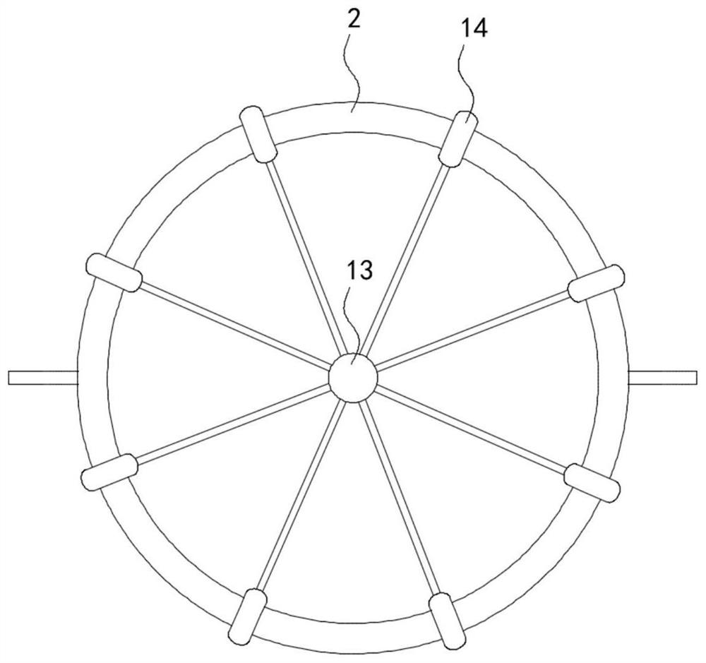
[0028] Such as Figure 4 As shown, the difference between this embodiment and Embodiment 1 is that the inner bottom surface of the box body 1 is rotatably connected with a vertically arranged rotating rod 13, and the upper end of the rotating rod 13 passes through the lifting plate 5 and the sealing plate 7 in sequence and connects with the box body. The inner top surface of the body 1 is rotationally connected, and the rotating rod 13 is provided with threads, and the rotating rod 13 is threadedly connected with the lifting plate 5, and a plurality of scrubbing rings 14 are slidingly sleeved outside the heating device 2, and the scrubbing rings 14 are connected to the rotating rod through the fixed rod. The rod 13 is fixedly connected.

[0029] A filter screen 15 is fixedly sleeved outside the rotating rod 13, and the filter screen 15 is arranged in an upwardly arched circular table shape. The filter screen 15 is made of stainless steel wire weaving. The side wall of the box ...


PUM


Abstract

The invention belongs to the field of household electrical appliances, and in particular relates to a self-cleaning and voltage-stabilized water heater based on the principle of high-temperature degaussing, which includes a box body, a heating device is arranged in the box body, and the upper end and the lower end of the box body are respectively fixed and communicated with inlet and outlet The water pipe and the water outlet pipe, the inside wall of the box body is sealed and slidably connected with a lifting plate, and the lifting plate is provided with two symmetrically arranged through holes, and the upper surface of the lifting plate is rotatably connected with a sealing plate. There are two water exchange holes respectively connected to the two through holes in the sealing plate. Both the lifting plate and the sealing plate are made of materials with a lower density than water. The outer ring of the sealing plate passes through the coil spring and the lifting plate. Fixed connection. The invention can prevent the cold water in the water tank from being in contact with hot water, resulting in a decrease in the temperature of the outlet water, and can always keep the water pressure in the tank unchanged, ensuring the normal use of the user, and can scrub the heating device through the scrubbing ring to prevent scale Adhesion buildup on the surface of the heating device.

Description

technical field [0001] The invention belongs to the field of household appliances, in particular to a self-cleaning and voltage-stabilizing water heater based on the principle of high-temperature degaussing. Background technique [0002] Electric water heaters can be divided into wall-mounted (horizontal) type electric water heaters and floor-mounted (vertical) water heaters according to the installation method. The water heater has the characteristics of convenient installation and large water output. [0003] When the traditional water heater is in use, as the hot water in the water tank decreases, the water pressure will decrease, resulting in a decrease in the water outlet speed of the outlet pipe, which will affect the normal use of the user, and the heating pipe in the existing water heater will be used for a period of time Finally, a layer of scale will adhere to the heating tube, which not only affects the heat exchange efficiency between the heating tube and the wa...

Claims


Application Information

Patent Timeline
Patent Type & Authority Patents(China)
IPC IPC(8): F24H9/18F28G3/00B01D33/01B01D33/54B01D33/56
CPCB01D33/0158B01D33/54B01D33/56F24H9/18F28G3/00
Inventor 刘胜芹周志强
Owner 聊城尚贤物资有限公司
Why Eureka
Try Eureka